Table of Contents
Advertisement
Advertisement
Table of Contents

Related Manuals for Laspaziale S2


Summary of Contents for Laspaziale S2
- Page 1 espresso coffee machines LSI 022 - Rev. 00 - Ed. 12/2015...
- Page 2 espresso coffee machines WEEE Disposal of the equipment by the users within the European Community (WEEE) in compliance with the article 13 of the legislative decree issued on 25 July 2005, nr 151 ”Implementation of the directives 2002/95/CE, 2002/96/CE e 2003/108/CE, concerning the decrease in the usage of dangerous substances in the electrical and electronic equipment and the disposal of waste”...
-
Page 3: Table Of Contents
espresso coffee machines INDEX 6. SETTING THE MOTOR PUMP PRESSURE .......... 21 1. GENERAL DESCRIPTION OF THE MACHINE ........4 DESCRIPTION OF DELIVERY COFFEE TOUCHPAD ....5 7. EK MODEL ALARMS OPERATION ............21 2. GENERAL ADVICE FOR THE INSTALLER ........... 6 8. -
Page 4: General Description Of The Machine
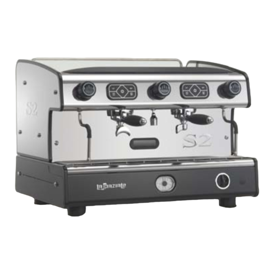
espresso coffee machines 1. GENERAL DESCRIPTION OF THE MACHINE 13 12 Fig. 1 LEGEND Top cup grid Drip tray grid 13. Gauge Steam delivery knob Water drip tray 14. Piezoelectric lighter for gas (o ptional) Touchpad Main on/off switch 15. Control knob for gas delivery (optional) Hot water dispensing knob 10. -
Page 5: Description Of Delivery Coffee Touchpad
espresso coffee machines 1.1 DESCRIPTION OF DELIVERY COFFEE TOUCHPAD Fig. 2 Fig. 3 LEGEND LEGEND 1 short coffee preset delivery button Delivery button 1 long coffee preset delivery button 2 short coffees preset delivery button 2 long coffees preset delivery button Continuous delivery key LSI 022 - Rev. -
Page 6: General Advice For The Installer
espresso coffee machines 2. GENERAL ADVICE FOR THE INSTALLER Read carefully the instructions and warnings contained in this manual and in the “USE AND MAINTENANCE MANUAL” , since they provide important indications concerning the installation of the appliance. Attention! This appliance may only be used for its intended purpose. Any other use is therefore considered as improper and unreasonable. - Page 7 espresso coffee machines Danger! If it becomes necessary to replace the machine’s power supply cable, utilise only these types: CET ELETRIC H07rn-f 5 x 2.5 mm (400v) for 2/3 group versions, 5 x 4 mm (400v) for 4 group versions - CET ELETRIC SINGLE PHASE 3 x 2.5 mm (220v) 2 group versions, 3 x 4 mm (220v) for 3/4 group versions.
- Page 8 espresso coffee machines Attention! The appliance must be installed on a flat bearing surface, the stability of which needs to be checked. Attention! The appliance must be installed where use and maintenance are restricted to trained staff. The electrical power system, water supply system and drainage system must prearranged by the customer in an ideal position to permit the correct installation.
-
Page 9: Removing The Packaging
espresso coffee machines 3. REMOVING THE PACKAGING After unpacking the machine, please check its integrity; in case of doubt, do not use it and consult the manufacturer. Packaging materials must not be left within children’s reach since they are potentially dangerous. Attention! The appliance weight is more than 30 kg and therefore, it cannot be moved by a single person alone. -
Page 10: Installation
espresso coffee machines 4. INSTALLATION Place the machine on the support surface, lifting it up only from underneath. Adjust the feet so that the machine fits perfectly in a horizontal position and tilting slightly backwards. Before connecting the machine to the supply systems, ensure that the data on the nameplates correspond to the ratings where the machine is installed. - Page 11 espresso coffee machines Danger! The light blue conductor lead of cable (A) is connected to the neutral phase of the electrical system. Below the electric diagram for 3 ph machine. V400/ 3Ph V230/ 3Ph V230/ 1Ph BLACK BLACK BLACK HEATING ELEMENT CONNECTION BROWN BROWN...
-
Page 12: Water Mains Installation Diagram
espresso coffee machines 4.2 WATER MAINS INSTALLATION DIAGRAM Attention! The machine is supplied without water in the boiler to avoid exposure to temperatures less than 0°C that could cause irreparable damage. Legend: 1. Water tap (previously installed by the customer) 2. -
Page 13: Drainage System
espresso coffee machines Danger! INSTALLATION OF THE WATER SOFTENER IS RECCOMENDED TO PRoLONG THE LIFE OF THE MACHINE. Install the water softener according to the instructions and norms supplied by the manufacturer. The water softener must be positioned where it is easily accessible so as to carry out the regeneration cycle when necessary and should be positioned near to the water drainage u-pipe. -
Page 14: Gas System Installation Diagram
espresso coffee machines 4.4 GAS SYSTEM INSTALLATION DIAGRAM Legend: 1. Gas Tap (previously installed by the customer). 2. Gas supply pipe. Fig. 7 Take note! The appliance has been equipped by the manufacturer to operate with IPG (G30). Only use pipes that are suitable for the type of gas used and compliant with the laws in force to connect the appliance to the system. - Page 15 espresso coffee machines GAS TABLE Ø HOLE Ø HOLE Rated Rated POWER POWER Consumption Consumption RATING RATING NOZZLE GAS TYPE Watt Kcal / h gr / h l / h Mod. 2 groups 1376 Mod. 3 groups 2500 2150 Take note! The nozzle hole (Ø) is given in hundredths of a millimeter.
-
Page 16: Switching On The Machine
espresso coffee machines 5. SWITCHING ON THE MACHINE 5.1 FILLING THE BOILER A. Open the water supply tap as arranged during the preparatory stages (see Fig. 6 on page 12 - Ref. 1). B. Verify that the water mains pressure (approx. 4 bar) is visualized on the water mains pressure gauge (12). 5.2 SWITCHING ON THE APPLIANCE A. - Page 17 espresso coffee machines Take note! Carry out this procedure to program the remaining doses, using the 1-cup filter holder (13) or the 2-cup one (5), according to the type of dose to be programmed. Take note! To quit the programming function, press the free flow delivery button (e) for 5 seconds or, alternatively, wait 1 minute to quit the function automatically.
-
Page 18: Electric Heating System
espresso coffee machines 5.5 OPERATING TEMPERATURE ADJUSTMENT FOR ELECTRIC HEATING SYSTEM The electric heating system of the machine is already set by the manufacturer to work at a temperature of 120 °C in the boiler, corresponding to 1 bar boiler pressure. This pressure can be viewed on the pressure gauge (12) on the appliance. In order to increase or decrease the boiler pressure, it is necessary to operate on the electric pressure switch (Fig. -
Page 19: Individual Temperature Control - I.t.c. - (Optional)
espresso coffee machines 5.6 INDIVIDUAL TEMPERATURE CONTROL - I.T.C. - (OPTIONAL) This system makes it possible to set a different coffee brewing temperature for Temperature each delivery group. regulator The temperature of each group is independent from the temperature set in the boiler. -
Page 20: Counter Function (Optional)
espresso coffee machines 5.8 COFFEE COUNTER FUNCTION (OPTIONAL) COUNTER function allows to record the number of cups of coffee that have been delivered by the machine. P.000000 T.000000 Once the machine is switched on, the display shows for a few seconds the date and then the partial and total counters. -
Page 21: Setting The Motor Pump Pressure
espresso coffee machines 6. SETTING THE MOTOR PUMP PRESSURE The proper working pressure ranges from 8 to 10 bar. This pressure can be viewed on the pressure gauge (12) on the appliance by switching on a delivery group. To adjust the pressure, turn the adjustment screw (1 - Fig. 13) of the motor pump, after loosening the lock nut (2 - Fig. -
Page 22: Hydraulic System
espresso coffee machines 9. HYDRAULIC SYSTEM WATER LAYOUT DIAGRAM LEGEND = WATER NET SUPPLY TAP = PRESSURE REDUCER (optional) = SOFTENER (optional) = WATER FILTER (optional) 3° GR 2° GR 1° GR MP = MOTORPUMP = NO RETURN VALVE = EXPANSION VALVE = WATER MAIN/PUMP GAUGE BOILER EVA = WATER REFILL SOLENOID VALVE... -
Page 23: Diagrams For Electronic Board Connections
espresso coffee machines 10. DIAGRAMS FOR ELECTRONIC BOARD CONNECTIONS LSI 022 - Rev. 00 - Ed. 12/2015... -
Page 24: Electrical Diagram
espresso coffee machines 11. ELECTRICAL DIAGRAM LSI 022 - Rev. 00 - Ed. 12/2015... -
Page 25: Key Diagram
espresso coffee machines 11.1 KEY DIAGRAM = Control board power supply = Motor pump = Cup warmer heating element = Boiler heating element EVAL = Solenoid valve automatic water refill = Solenoid valve, 1 group from the right = Solenoid valve, 2 group from the right = Solenoid valve, 3 group from the right... - Page 26 Steam which heats up cold water Hot water outlet for coffee delivery Steam taking pipe Hot water transit for coffee delivery Steam Hot water Cold water inlet into the boiler Boiler heating element http://www.laspaziale.com/index.php/en/video LSI 022 - Rev. 00 - Ed. 12/2015...
- Page 27 espresso coffee machines Fig. 14 DIMENSIONS AND WEIGHT POWER SUPPLY RATING AND ABSORPTION 1 GR 2 GR 3 GR SPAZIO 1 GR 2 GR 3 GR SPAZIO VOLT 220/240 220/240 220/240/400 220/240 50/60 50/60 50/60 50/60 2200 3900 4500 3000 WEIGHT KGS 3000 6500...
- Page 28 espresso coffee machines...
Need help?
Do you have a question about the S2 and is the answer not in the manual?
Questions and answers