Table of Contents
Advertisement
Quick Links
Advertisement
Table of Contents

Related Manuals for Burkert 0212 B


Summary of Contents for Burkert 0212 B
- Page 1 Type 0212 B 2/2-Way solenoid valve Operating Instructions...
-
Page 2: Table Of Contents
OPERATING INSTRUCTIONS Contents The operating instructions describe the entire life cycle of the device. Keep Operating Instructions ............... 2 these instructions in a location which is easily accessible to every user Symbols .................... 3 and make these instructions available to every new owner of the device. Intended USE .................. -
Page 3: Symbols
SYMBOLS INTENDED USE The following symbols are used in these instructions. WARNING! DANGER! Incorrect use of the solenoid valve Type 0212 may be dangerous to people, nearby equipment and the environment. Warns of an immediate danger! ▶ When using the device, always observe the permissible data speci- ▶... -
Page 4: General Safety Instructions
GENERAL SAFETY INSTRUCTIONS WARNING! DANGER! Risk of injury from unintentional activation. ▶ Take appropriate measures to prevent unintentional activation! Danger of injury - high pressure. ▶ Before loosening the lines and valves, turn off the pressure and vent the lines! WARNING! Risk of electric shock. -
Page 5: Designs With Explosion Protection
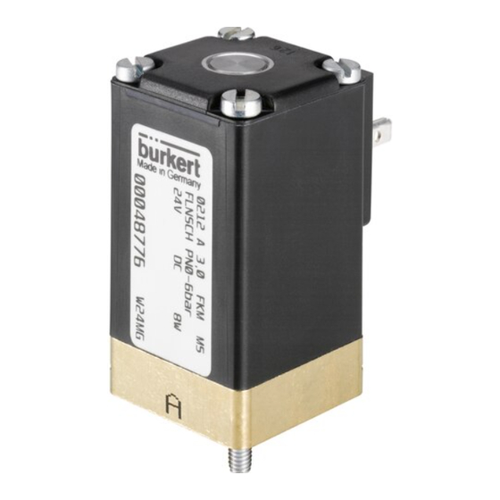
TECHNICAL DATA Operate the device only when it is in perfect condition and in accordance with the operating instructions. Design and Function Failure to observe this operating manual and its operating instruc- 5.1.1 Structure tions as well as unauthorised tampering with the device release us from any liability and also invalidte the warranty covering the device Type 0212-B is a direct action 2/2-way lifting armature solenoid valve and accessories! -
Page 6: Mechanical Data
5.3 Mechanical Data 5.4 Pneumatic Data Dimensions Operating principle 2/2-way valve, direct action B (NO) Pressure range Pressure range Pressure range Nominal width for AC [bar] for DC [bar] 0-12 0-12 0-12 0-12 0-12 0-10 0-10 Line connections Bürkert flange 001-01-06 (32×32) Note the information specified on the rating plate for voltage, Housing material Brass, stainless steel, polyamide... -
Page 7: Electrical Data
230 V 50 - 60 Hz Type 240 V 50 - 60 Hz Voltage tolerance ± 10 % 0212 B 3,0 FKM MS Coil power consumption AC 21 VA (closed), FLNSCH PN0-6bar 12 VA / 8 W (operation) Nominal operating mode in continuous operation ED 100%,... -
Page 8: Installation
INSTALLATION To ensure a longer service life for the device, we recommend an installation position with the magnet system pointing up, since Safety Instructions this will prevent falling materials from getting into the core area. Installation on a connection plate: WARNING! →... -
Page 9: Electrical Installation
6.3 Electrical Installation → Connect valve output A with connection A (B) of the connection plate: Either screw the valves onto the connection plate and then DANGER! fasten the connection plate from below with M5 screws or fasten the connection plate from above with M4 cylinder head screws and Risk of electric shock when reaching into the equipment! then screw on the valves. -
Page 10: Maintenance / Malfunctions
MAINTENANCE / MALFUNCTIONS REPLACEMENT PARTS The valve is maintenance-free under normal operating conditions. CAUTION! Using the wrong accessories or replacement parts may be Malfunctions dangerous! If malfunctions occur, check The wrong accessory or unsuitable replacement parts may cause → the line connections injuries and damage to the device or the area around it. -
Page 11: Packaging, Transport, Storage
PACKAGING, TRANSPORT, STORAGE NOTE! Transport and storage damage! • Protect the device against moisture and dirt in shock-resistant pack- aging during transportation and storage. • Permitted storage temperature: -20...+55°C. Damage to the environment caused by device components con- taminated with media. •... - Page 12 Fax + 49 (0) 7940 - 10-91 448 E-mail: info@de.burkert.com International address www.burkert.com Manuals and data sheets on the Internet : www.burkert.com Bedienungsanleitungen und Datenblätter im Internet: www.buerkert.de Manuels d'utilisation et fiches techniques sur Internet: www.buerkert.fr © Bürkert Werke GmbH & Co. KG, 2017 Operating Instructions 1710/02_EU-ML_00805662 / Original DE www.burkert.com...
Need help?
Do you have a question about the 0212 B and is the answer not in the manual?
Questions and answers