Table of Contents
Advertisement
Available languages
Available languages
PTB 03 ATEX 5014 X
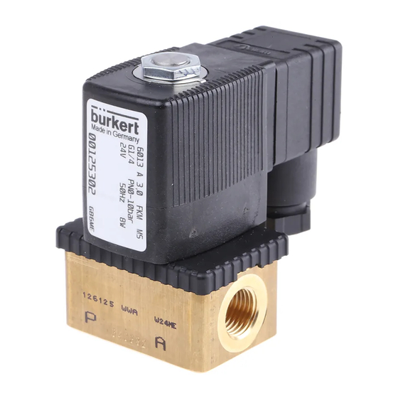
Type 0641 / 2832 / 6013 / 6022
Solenoid valve for use in the gas feedback systems
for petrol pumps
Magnetventile zum Einsatz in
Gasrückführungssystemen von Tanksäulen
Electrovannes pour emploi dans systèmes de
recyclage de gaz de distributeurs de carburant
Operating Instructions
Bedienungsanleitung
Manuel d'utilisation
Unit 173 Argyle Industrial Estate, Argyle Street, Nechells, Birmingham B7 5TE
www.pneutrolfluidcontrol.com sales@pneutrol.com
Pneutrol International Limited
Tel.. +44 (0) 1213287288
Example
Beispiel
Exemple
Type 0641
Advertisement
Chapters
Table of Contents

Subscribe to Our Youtube Channel
Related Manuals for Burkert 0641


Summary of Contents for Burkert 0641
- Page 1 PTB 03 ATEX 5014 X Type 0641 / 2832 / 6013 / 6022 Solenoid valve for use in the gas feedback systems for petrol pumps Magnetventile zum Einsatz in Gasrückführungssystemen von Tanksäulen Electrovannes pour emploi dans systèmes de recyclage de gaz de distributeurs de carburant...
- Page 2 We reserve the right to make technical changes without notice. Technische Änderungen vorbehalten. Sous réserve de modifications techniques. © 2003 - 2011 Bürkert Werke GmbH Operating Instructions 1107/07_EU-ML_00804694 / Original DE...
- Page 3 Electrovannes avec homologation pour emploi dans des systèmes de recyclage des gaz de distributeurs de carburant Valve with cast-on cable with terminal box Ventil mit eingegossener Leitung mit Klemmkasten Vanne avec câble de raccordement avec boîte à bornes Type 0641 Type 2832 03 ATEX5014 X - 3...
- Page 4 Valve with cast-on cable with terminal box Ventil mit eingegossener Leitung mit Klemmkasten Vanne avec câble de raccordement avec boîte à bornes Type 6013 Type 6022 4 - 03 ATEX5014 X...
-
Page 5: Table Of Contents
2.1 Special conditions ....................10 2.2 Marking of the units ....................12 3 TECHNICAL DATA ........................13 3.1 Technical data for the type 0641 and 2832 units ..........14 3.2 Technical data for the type 6013 and 6022 units ..........16 4 INSTALLATION AND COMMISSIONING ................ 18 4.1 Assembly ........................19... -
Page 6: General Information
GENERAL INFORMATION 1.1 The operating instructions The operating manual describes the whole life cycle of the appliance. Store this manual in such a way that is easily accessible to every user and is avai- lable to every new owner of the appliance. WARNING! The operating manual must be read and understood. -
Page 7: Correct Utilisation
Bürkert will accept no liability for any damage resulting from such use. The user must bear all the risk alone. 1.3.1 Approvals of the electromagnets Valve type Electromagnet Approval 0641 64.- PTB 02 ATEX 2094X 2832 6013 Typ AC10-..-.-PD47 +... -
Page 8: General Safety Instructions
1.4 General Safety Instructions DANGER! Risk of explosion if the device is opened! • The device is a sealed system. It must not be opened. DANGER! Electrical power supply in the system! Acute risk of injury from hazardous structure-borne voltage! Risk of damage to the device due to short circuit! •... -
Page 9: General Information
PTB (Physikalisch Technische Bundesanstalt) Bundesallee 100 38116 Braunschweig who also audited the manufacture (CE0102). 1.5.4 Information on the Internet Operating instructions and data sheets for type 0641 (2832/6013/6022) may be found on the Internet under: www.buerkert.com 03 ATEX5014 X - 9... -
Page 10: Application Conditions For The Units
(normally 1500 A). For the valve types 0641, 2832, 6013 and 6022 in the versions without fuses, the short-circuit protection must be guaranteed by the operator. For the version with a fuse, the latter is built into the terminal box of the device. - Page 11 The valves may only be dismantled by the manufacturer. The always represent a closed system! The Type 0641, 2832, 6013 and 6022 solenoid valves (Inner Zone 0) are used for explosive steam/air mixtures in the in gas feedback equipment of filling stations.
-
Page 12: Marking Of The Units
Valve Marking 1 Marking 2 type (Magnetic coil) (Complete unit) 0641 Approval PTB 02 ATEX 2094X PTB 03 ATEX 5014X 2832 Protection II 2G Ex m II T4, T5 II 1/2G Ex m II T3... -
Page 13: Technical Data
Space for barcode Valve type Code for the marking of units for use in the gas feedback sys- tems of petrol pumps ( Coil size 0641 / 2832 PD 36 6013 / 6022 PD 97 03 ATEX5014 X - 13... -
Page 14: Technical Data For The Type 0641 And 2832 Units
3.1 Technical data for the type 0641 and 2832 units Temperature class Electromagnet used Type 64.-, PTB 02 ATEX 2094X Circuit function of the valve A = normally closed Type of current Universal current (0 Hz ... 60 Hz) Rated voltage 12 V ... - Page 15 3.1.1 Marking of the mounted solenoid valves The letters A, L and K are used to differentiate between the electrical con- nection variants for the electromagnets. Internal code: The internal code is used for the marking of the mounted solenoid valves. Marking Version Internal...
-
Page 16: Technical Data For The Type 6013 And 6022 Units
3.2 Technical data for the type 6013 and 6022 units Temperature class T3 Electromagnet Type AC10, PTB 00 ATEX 2129X used Circuit function of A = normally closed the valve Type of current Universal current (0 Hz ... 60 Hz) Rated voltage 12 V ... - Page 17 3.2.1 Identification of the electrical connection variants with terminal box The variable codes given in the following table are used for the marking of the electrical connection variants. Electrical connection variants Variable code dependet on the - Supply line / cable lin line length - Terminal box with M 20 x 1.5 cable gland, JA02...
-
Page 18: Installation And Commissioning
INSTALLATION AND COMMISSIONING DANGER! Danger of explosion! • The device is a sealed system. The unit must not be dismantled! The following safety regulations must be observed: • The surface of the device may develop an electrostatic charge. In areas with an explosion hazard, the surface of the units may only be cleaned with a damp cloth! •... -
Page 19: Assembly
Observe the applicable accident prevention and safety regulations for pneumatic systems! The type 0641, 2832, 6013 and 6022 units may only be installed in petrol pumps between the pump valve and the gas feedback pump. This use must be based on EN 60079-14. -
Page 20: Commissioning
4.2 Commissioning Before commissioning, ensure that • The device has been correctly installed, • The connections have been correctly made, • The device is not damaged, • All bolts are securely tightened. MAINTENANCE AND FAULTS DANGER! Hazards due to improper service, repair and maintenance work. •... -
Page 21: Accessories
ACCESSORIES For electromagnet models with terminal boxes, fuses of the Type 1058 with approval PTB 01 ATEX 2064 U can be used in Temperature Class T4. Fuse type 1058 Order No. 0,063 A 153717 0,080 A 153745 0,100 A 153718 0,125 A 153719 0,160 A... - Page 22 22 - 03 ATEX5014 X...
- Page 23 2.1 Besondere Bedingungen ..................28 2.2 Kennzeichnung der Geräte ..................30 3 TECHNISCHE DATEN ......................31 3.1 Technische Daten der Typen 0641 und 2832 ...........32 3.2 Technische Daten der Typen 6013 und 6022 ...........34 4 MONTAGE / INBETRIEBNAHME ..................36 4.1 Montage ........................37 4.2 Inbetriebnahme ......................38...
-
Page 24: Allgemeines
ALLGEMEINES 1.1 Die Bedienungsanleitung Die Bedienungsanleitung beschreibt den gesamten Lebenszyklus des Ge- rätes. Bewahren Sie diese Anleitung so auf, dass sie für jeden Benutzer gut zugänglich ist und jedem neuen Eigentümer des Gerätes wieder zur Verfü- gung steht. WARNUNG! Die Bedienungsanleitung muss gelesen und verstanden werden •... -
Page 25: Bestimmungsgemäße Verwendung
• Eine andere oder darüber hinausgehende Benutzung gilt als nicht bestimmungsgemäß. Für hieraus resultierende Schäden haftet Bürkert nicht. Das Risiko trägt allein der Anwender. 1.3.1 Zulassungen der Elektromagnete Ventiltyp Elektromagnet Zulassung 0641 64.- PTB 02 ATEX 2094X 2832 6013 Typ AC10-..-.-PD47 + PTB 00 ATEX 2129X... -
Page 26: Allgemeine Sicherheitshinweise
1.4 Allgemeine Sicherheitshinweise GEFAHR! Explosionsgefahr durch Öffnen des Gerätes! • Das Gerät ist ein geschlossenes System. Es darf nicht demontiert werden. GEFAHR! Elektrische Spannung im System! Akute Verletzungsgefahr durchgefährliche Körperspannung! Gefahr der Beschädigung des Gerätes durch Kurzschluss! • Arbeiten am elektrischen System dürfen nur von ausgebildeten Elektro- fachkräften durchgeführt werden! •... -
Page 27: Allgemeine Hinweise
Die EG-Baumusterprüfbescheinigung PTB 03 ATEX 5014 X wurde von der PTB (Physikalisch Technische Bundesanstalt) Bundesallee 100 38116 Braunschweig ausgestellt, die auch die Fertigung auditiert (CE0102). 1.5.4 Informationen im Internet Bedienungsanleitungen und Datenblätter zum Typ 0641 (2832/6013/6022) finden Sie im Internet unter: www.buerkert.de 03 ATEX5014 X - 27... -
Page 28: Einsatzbedingungen Der Geräte
Geräts eingebaut. Nähere Beschreibung der Ausführungen finden Sie im Abschnitt Technische Daten der verschiedenen Ausführungen. Sicherung ..A 2.1.2 Konformität Der Typ 0641, 2832, 6013 und 6022 ist konform zu den EG Richtlinien entsprechend der EG-Konformitätserklärung. 2.1.3 Normen Durch folgende Normen wird die Konformität des mit den EG-Richtlinien erfüllt:... - Page 29 Explosionsgefahr durch Öffnen des Gerätes! • Das Gerät ist ein geschlossenes System. Es darf nicht demontiert werden. Die Magnetventile Typ 0641, 2832, 6013 und 6022 (Inneres Zone 0) die- nen zur Steuerung explosionsfähiger Dampf-/Luftgemische in Gasrückfüh- rungseinrichtungen von Tankstellen. blockverschraubt Typ 0641 und Typ 2832 Die Magnetspule 64.- ist mit 4 versiegelten Zylinderschrauben M4x59 auf...
-
Page 30: Kennzeichnung Der Geräte
Die Zusammensetzung des Zündschutzartenkennzeichens richtet sich nach den Zündschutzarten der jeweils verwendeten Komponenten. Ventil- Kennzeichnung 1 Kennzeichnung 2 (Magnetspule) (Komplettgerät) 0641 Zulassung PTB 02 ATEX 2094X PTB 03 ATEX 5014X 2832 Zünd- II 2G Ex m II T4, T5 II 1/2G Ex m II T3 schutzart bzw. -
Page 31: Technische Daten
Platz für Barcode Ident-Nr. der Spule - Herstelldaten Platz für Barcode Ventiltyp Code zur Kennzeichnung der Geräte für den Einsatz in Gas- rückführungssystemen von Tanksäulen (Spulengröße) 0641 / 2832 PD 36 6013 / 6022 PD 97 03 ATEX5014 X - 31... -
Page 32: Technische Daten Der Typen 0641 Und 2832
3.1 Technische Daten der Typen 0641 und 2832 Temperaturklasse Vewendeter Elektromagnet Typ 64.-, PTB 02 ATEX 2094X Wirkungsweise des Ventils A = stromlos geschlossen Stromart Universalstrom (0 Hz ... 60 Hz) Bemessungsspannung 12 V ... 240 V (±10 %) Bemessungsstrom 0,58 ...0,034 A... - Page 33 3.1.1 Kennzeichnung der aufgebauten Magnetventile Zur Unterscheidung der Varianten der elektrischen Anschlüsse der Elektro- magnete werden die Buchstaben A, L und K verwendet. Interner Code: Der Interne Code dient zur Kennzeichnung der aufgebauten Magnetventile. Kenn- Ausführung Interner zeichnung Code - Fest eingebaute Gummischlauchleitung des Ohne Typs H05 RN-F3G 0,75 Angabe...
-
Page 34: Technische Daten Der Typen 6013 Und 6022
3.2 Technische Daten der Typen 6013 und 6022 Temperaturklasse Vewendeter Typ AC10, PTB 00 ATEX 2129X Elektromagnet Wirkungsweise A = stromlos geschlossen des Ventils Stromart Universalstrom (0 Hz ... 60 Hz) Bemessungs- 12 V ... 400 V (±10 %) spannung Spulengröße 5 Spulengröße 6 Bemessungs-... - Page 35 3.2.1 Kennzeichnung der elektrischen Anschlussvarianten mit Klemmenkasten Zur Kennzeichnung der elektrischen Anschlussvarianten werden die varia- blen Codes gemäß folgender Tabelle verwendet. Elektrische Anschlussvarianten Variabler Code abhängig von - Zuleitung/Kabelschwanz der Leitungs länge - Klemmenkasten mit Kabelverschraubung M 20 x 1,5; JA02 ohne Sicherung - Klemmenkasten mit Gewindenippel M 20 x 1,5;...
-
Page 36: Montage / Inbetriebnahme
MONTAGE / INBETRIEBNAHME GEFAHR! Explosionsgefahr! • Das Gerät ist ein geschlossenes System. Es darf nicht demontiert werden. Folgende Sicherheitsfestlegungen sind einzuhalten: • Die Oberfläche des Gerätes kann sich elektrostatisch aufladen. In explosionsgefährdeten Bereichen darf die Oberfläche der Geräte nur mit einem feuchten Tuch gereinigt werden! •... -
Page 37: Montage
• Geltende Unfallverhütungs- und Sicherheitsbestimmungen für pneuma- tische Geräte beachten! Die Geräte Typ 0641, 2832, 6013 und 6022 dürfen nur in Zapfsäulen zwi- schen dem Zapfventil und der Gasrückführungspumpe errichtet werden. Dabei ist die EN 60079-14 zugrunde zu legen. Der maximal zulässige Umgebungstemperaturbereich ist zu beachten. -
Page 38: Inbetriebnahme
4.2 Inbetriebnahme Stellen Sie vor Inbetriebnahme sicher, dass • das Gerät vorschriftmäßig installiert wurde, • der Anschluss ordnungsgemäß ausgeführt wurde, • das Gerät nicht beschädigt ist, • alle Schrauben fest angezogen sind. WARTUNG UND FEHLERBEHEBUNG GEFAHR! Gefahr durch unsachgemäße Wartungs-, Reparatur- und Instandhal- tungsarbeiten! •... -
Page 39: Zubehör
ZUBEHÖR Bei Ausführung der Geräte mit Klemmkasten kann in Temperaturklasse T4, die Sicherung des Typs 1058 mit Zulassung PTB 01 ATEX 2064 U einge- setzt werden. Sicherung Typ 1058 Bestell.-Nr. 0,063 A 153717 0,080 A 153745 0,100 A 153718 0,125 A 153719 0,160 A 153720... - Page 40 40 - 03 ATEX5014 X...
- Page 41 2.2 Marquage des appareils ..................48 3 CARACTERISTIQUES TECHNIQUES ................49 3.1 Caractéristiques techniques de l‘appareil de type 0641 et 2832 ....50 3.2 Caractéristiques techniques de l‘appareil de type 6013 et 6022 ....52 4 MONTAGE ET MISE EN SERVICE ..................54 4.1 Montage ........................55...
-
Page 42: Indications Generales
INDICATIONS GENERALES 1.1 Les consignes d‘utilisation Les consignes d’utilisation décrivent l’ensemble du cycle de vie de l’appareil. Veuillez conserver ces consignes de telle sorte qu’elles soient facilement accessibles à tous les utilisateurs et puissent être mises à la disposition de tout nouveau propriétaire de l’appareil. -
Page 43: Usage Conforme À La Destination
à la destination. Bürkert décline alors toute responsabilité pour les dégâts susceptibles d’en résulter. Le risque est à la charge de l’utilisateur seul. 1.3.1 Homologation des électro-aimants Type de vanne Electro-aiment Homologation 0641 64.- PTB 02 ATEX 2094X 2832 6013 Typ AC10-..-.-PD47 + PTB 00 ATEX 2129X... -
Page 44: Consignes De Sécurité
1.4 Consignes de sécurité DANGER! Risque d’explosion en cas d’ouverture de l’appareil! • L’appareil est un système fermé. Il ne doit pas être démonté. DANGER! Tension électrique dans le système! Risque de blessure grave en raison d’une tension corporelle dangereuse! Risque de dommages matériels (appareil) en cas de court-circuit! •... -
Page 45: Indications Générales
Bundesallee 100 38116 Braunschweig qui a également auditionné la fabrication (CE0102). 1.5.4 Informations dans Internet Vous trouverez les instructions de service et la fiche technique de type 0641 (2832/6013/6022) sur Internet à l‘adresse : www.buerkert.fr 03 ATEX5014 X - 45... -
Page 46: Conditions D'emploi Des Appareils
être égal ou supérieur au courant de court-circuit supposé au lieu de montage (habituelle-ment 1500 A). Dans le cas des types de vanne 0641, 2832, 6013 et 6022 dans les ver- sions sans fusible, la protection contre les courts-circuits doit être assurée par l’exploitant. - Page 47 Les vannes ne doivent être démontées que par le fabricant. Elles con- stituent toujours un système fermé. Les électrovannes type 0641, 2832, 6013 et 6022 (zone intérieure 0) ser- vent à commander des mélanges détonants vapeur/air dans des dispositifs de recyclage des gaz de stations-service.
-
Page 48: Marquage Des Appareils
La composition du marquage de protection „e“ est axée sur le mode de protection „e“ des composants respectivement utilisés. Type de Marquage 1 Marquage 2 vanne (bobine d‘électro-aimant) (appareil complet) 0641 Homolo- PTB 02 ATEX 2094X PTB 03 ATEX 5014X 2832 gation Protection II 2G Ex m II T4, T5 II 1/2G Ex m II T3 „e“... -
Page 49: Caracteristiques Techniques
N° d‘identification - date de production Place pour Code Type de Vanne Code pour marquage des appareils pour emploi dans système de recyclage des gaz de stations-service (Taille de bobine) 0641 / 2832 PD 36 6013 / 6022 PD 97 03 ATEX5014 X - 49... -
Page 50: Caractéristiques Techniques De L'appareil De Type 0641 Et 2832
3.1 Caractéristiques techniques de l‘appareil de type 0641 et 2832 Classe de température Electro-aimant utilisé Type 64.-, PTB 02 ATEX 2094X Mode de fonctionne-ment A = fermée sans courant de la vanne Type de courant Courant universel (0 Hz ... 60 Hz) Tension de calcul 12 V ... - Page 51 3.1.1 Marquage les électrovannes montées Pour distinguer les variantes de raccordement électrique des électro-ai- mants, les lettres A, L et K sont utilisées. Code interne: Le code interne sert à marquer les électrovannes montées Marquage Version Code interne - Conduite souple en caoutchouc montée à sans in- demeure du type H05 RN-F3G 0,75 dication...
-
Page 52: Caractéristiques Techniques De L'appareil De Type 6013 Et 6022
3.2 Caractéristiques techniques de l‘appareil de type 6013 et 6022 Classe de tempé- rature Electro-aimant Type AC10, PTB 00 ATEX 2129X utilisé Mode de foncti- onne-ment de la A = fermée sans courant vanne Type de courant Courant universel (0 Hz ... 60 Hz) Tension de calcul 12 V ... - Page 53 3.2.1 Indentification des variantes de raccordement électrique avec une boîte de bornes Pour distinguer les variantes de raccordement électrique, les codes varia- bles sont utilisés selon la table ci-après. Variantes de raccordement électrique Code variable en fonction de - Ligne d‘amenée/queue de câble la longueur de ligne - Boîte de bornes avec passe-câble à...
-
Page 54: Montage Et Mise En Service
MONTAGE ET MISE EN SERVICE DANGER! Danger d‘explosion! • L’appareil est un système fermé. L‘appareil ne doit pas être démonté! Il faut respecter les prescriptions de sécurité suivantes: • La surface de l’appareil peut emmagasiner une charge électrostatique. Dans les zones à risques de déflagration, la surface des appareils ne doit être nettoyée qu’avec un linge humide! •... -
Page 55: Montage
Respecter les règles de prévention des accidents et de sécurité en vigueur pour les appareils pneumatiques! Les appareils type 0641, 2832, 6013 et 6022 ne doivent être montés unique-ment que dans des distributeurs de carburant entre le pistolet distri- buteur et la pompe de recyclage des gaz. Se baser sur la norme EN 60079-14. -
Page 56: Mise En Service
4.2 Mise en service Avant la mise en service, assurez-vous que : • l’appareil a été installé de manière conforme, • le branchement a été réalisé comme il convient, • l’appareil n’est pas endommagé, • toutes les vis sont convenablement serrées. MAINTENANCE ET DERANGEMENTS DANGER! Risques induits par les travaux de maintenance, de réparation et de... -
Page 57: Accessoires
ACCESSOIRES Dans la version des électro-aimants avec boîte de bornes, le fusible de type 1058 avec homologation PTB 01 ATEX 2064 U peut être utilisé en classe de température T4. Type de fusible 1058 N° de commande. 0,063 A 153717 0,080 A 153745 0,100 A... - Page 58 www.pneutrolfluidcontrol.com Pneutrol International Limited Unit 173 Argyle Industrial Estate, Argyle Street, Nechells, Birmingham B7 5TE www.pneutrolfluidcontrol.com sales@pneutrol.com Tel.. +44 (0) 1213287288...
Need help?
Do you have a question about the 0641 and is the answer not in the manual?
Questions and answers