
Related Manuals for Huawei ETP48400-C3B1


Summary of Contents for Huawei ETP48400-C3B1
- Page 1 ETP48400-C3B1, ETP48400-C3B2 Embedded Power User Manual Issue Date 2023-05-30 HUAWEI TECHNOLOGIES CO., LTD.
- Page 2 Notice The purchased products, services and features are stipulated by the contract made between Huawei and the customer. All or part of the products, services and features described in this document may not be within the purchase scope or the usage scope. Unless otherwise specified in the contract, all statements, information, and recommendations in this document are provided "AS IS"...
-
Page 3: About This Document
Indicates a potentially hazardous situation which, if not avoided, could result in equipment damage, data loss, performance deterioration, or unanticipated results. NOTICE is used to address practices not related to personal injury. Issue 08 (2023-05-30) Copyright © Huawei Technologies Co., Ltd. -
Page 4: Change History
Issue 02 (2019-10-25) Added the description about DCDB parameter settings. Deleted the description about the app. Issue 01 (2019-05-30) This issue is the first official release. The SMU software version is SMU V500R003C00. Issue 08 (2023-05-30) Copyright © Huawei Technologies Co., Ltd. -
Page 5: Table Of Contents
4.7 Installing a Communications Expansion Module NIM01C3...................50 4.8 Installing a Communications Expansion Module CIM02C..................52 4.9 (Optional) Installing Dry Contact Signal Cables......................52 4.10 (Optional) Installing Communications Cables......................53 4.10.1 WebUI Management..............................53 Issue 08 (2023-05-30) Copyright © Huawei Technologies Co., Ltd. - Page 6 6.12.3 (Optional) Setting Parameters Before Using NetEco..................95 6.12.4 (Optional) Setting Parameters Before Using SNMP Management............... 97 6.13 Connecting the AC Power Supply..........................98 6.14 Subsequent Operations..............................99 7 Maintenance.........................100 7.1 Routine Maintenance................................ 100 Issue 08 (2023-05-30) Copyright © Huawei Technologies Co., Ltd.
- Page 7 D Electrical Conceptual Diagrams..................123 E Associations Between UIM Dry Contacts and Alarms..........124 F How Do I Change the Communications Protocol for COM4 and COM5?....126 G Acronyms and Abbreviations................... 128 Issue 08 (2023-05-30) Copyright © Huawei Technologies Co., Ltd.
-
Page 8: Safety Information
Equipment damage due to force majeure such as earthquakes, floods, volcanic eruptions, debris flows, lightning strikes, fires, wars, armed conflicts, typhoons, hurricanes, tornadoes, and extreme weather conditions ● Operation beyond the conditions specified in this document Issue 08 (2023-05-30) Copyright © Huawei Technologies Co., Ltd. -
Page 9: Personal Safety
D ANGER During operations, use dedicated insulated tools to prevent electric shocks or short circuits. The insulation and voltage resistance must comply with local laws, regulations, standards, and specifications. Issue 08 (2023-05-30) Copyright © Huawei Technologies Co., Ltd. -
Page 10: General Requirements
– Trained personnel: personnel who are trained in technology and safety, have required experience, are aware of possible hazards on themselves in Issue 08 (2023-05-30) Copyright © Huawei Technologies Co., Ltd. -
Page 11: Electrical Safety
WARNING For the equipment that needs to be grounded, install the ground cable first when installing the equipment and remove the ground cable last when removing the equipment. Issue 08 (2023-05-30) Copyright © Huawei Technologies Co., Ltd. - Page 12 ● After the installation is complete, ensure that protective cases, insulation tubes, and other necessary items for all electrical components are in position to avoid electric shocks. Issue 08 (2023-05-30) Copyright © Huawei Technologies Co., Ltd.
- Page 13 When routing power cables, ensure that there is no coiling or twisting. Do not join or weld power cables. If necessary, use a longer cable. ● Ensure that all cables are properly connected and insulated, and meet specifications. Issue 08 (2023-05-30) Copyright © Huawei Technologies Co., Ltd.
-
Page 14: Electrostatic Discharge (Esd)
When touching the equipment and handling boards, modules with exposed circuit boards, or application-specific integrated circuits (ASICs), observe ESD protection regulations and wear ESD clothing and ESD gloves or a well- grounded ESD wrist strap. Issue 08 (2023-05-30) Copyright © Huawei Technologies Co., Ltd. -
Page 15: Environment Requirements
Ensure that no liquid enters the equipment to prevent faults or short circuits. Issue 08 (2023-05-30) Copyright © Huawei Technologies Co., Ltd. - Page 16 Install rodent guards at the door of the equipment room to prevent rodents and insects from entering the room. ● After installing the equipment, remove the packing materials such as cartons, foam, plastics, and cable ties from the equipment area. Issue 08 (2023-05-30) Copyright © Huawei Technologies Co., Ltd.
-
Page 17: Mechanical Safety
Do not perform operations such as arc welding and cutting on the equipment without evaluation by the Company. ● Do not install other devices on the top of the equipment without evaluation by the Company. Issue 08 (2023-05-30) Copyright © Huawei Technologies Co., Ltd. - Page 18 The tilt angle α of the packed cabinet must be less than or equal to 15°. After the cabinet is unpacked, its tilt angle α must be less than or equal to 10°. Issue 08 (2023-05-30) Copyright © Huawei Technologies Co., Ltd.
-
Page 19: Working At Heights
● Behave cautiously when working at heights. Do not rest at heights. Using Ladders ● Use wooden or insulated ladders when you need to perform live-line working at heights. Issue 08 (2023-05-30) Copyright © Huawei Technologies Co., Ltd. - Page 20 If a single ladder is used, do not climb higher than the fourth rung of the ladder from the top. ● If you use a single ladder to climb up to a platform, ensure that the ladder is at least 1 m higher than the platform. Issue 08 (2023-05-30) Copyright © Huawei Technologies Co., Ltd.
-
Page 21: Battery Safety
To avoid leakage, smoke, flammable gas release, thermal runaway, fire, or explosion, do not disassemble, alter, or damage batteries, for example, insert sundries into batteries, squeeze batteries, or immerse batteries in water or other liquids. Issue 08 (2023-05-30) Copyright © Huawei Technologies Co., Ltd. - Page 22 Before putting into operation, ensure that fire fighting facilities that comply with local laws, regulations are installed. Issue 08 (2023-05-30) Copyright © Huawei Technologies Co., Ltd.
- Page 23 ● After being installed and connected to the system, the batteries are not powered on in time due to your reasons, which causes damage to the batteries due to overdischarge. Issue 08 (2023-05-30) Copyright © Huawei Technologies Co., Ltd.
- Page 24 Otherwise, a battery alarm will be generated and batteries may be damaged. ● Do not short-circuit the battery loop. A short circuit automatically triggers battery protection. Repeated short circuits may lead to battery faults and other risks including fire. Issue 08 (2023-05-30) Copyright © Huawei Technologies Co., Ltd.
-
Page 25: Short Circuit Protection
The actual specifications may vary depending on external factors, such as temperature, transportation, and storage. Short-Circuit Protection ● When installing and maintaining batteries, wrap the exposed cable terminals on the batteries with insulation tape. Issue 08 (2023-05-30) Copyright © Huawei Technologies Co., Ltd. - Page 26 Do not place waste batteries in environments with high humidity or corrosive substances. ● Do not use faulty batteries. Contact a battery recycling company to scrap them as soon as possible to avoid environmental pollution. Issue 08 (2023-05-30) Copyright © Huawei Technologies Co., Ltd.
-
Page 27: Product Overview
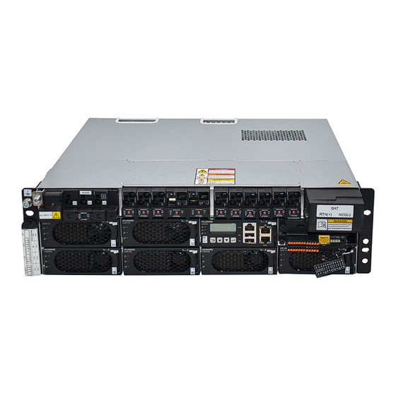
AC power into DC power. They supply –48 V or –57 V constant voltage to load equipment. The maximum capacity of the ETP48400-C3B1 is 24 kW, and the maximum capacity of the ETP48400-C3B2 is 18 kW. They apply to newly built sites as well as capacity expansion and reconstruction of existing sites. - Page 28 (8/20 µs) in common mode (Optional) Intelligent Power Distribution Unit Figure 2-3 DCDB48-200-16B appearance (1) Ground screw (2) LLVD power distribution (3) BLVD power distribution (4) DMU02C1 (5) DC input ports Issue 08 (2023-05-30) Copyright © Huawei Technologies Co., Ltd.
- Page 29 An alarm is generated. Table 2-3 Communication port description Communications Communications Communications Port Parameter Protocol COM1/COM2 Baud rate: 9600 bit/s Modbus protocol NOTE All these ports are protected by a security mechanism. Issue 08 (2023-05-30) Copyright © Huawei Technologies Co., Ltd.
- Page 30 ● When multiple DCDB48-200-16Bs are cascaded, you need to set the address DIP switch for the DMU02C1. ● If one DCDB48-200-16B is installed, you do not need to set the address DIP switch for the DMU02C1. Issue 08 (2023-05-30) Copyright © Huawei Technologies Co., Ltd.
- Page 31 43.6 mm x 482.6 mm x 255 mm x W x D) Weight ≤ 10 kg Installation Installed in a 19-inch rack mode Cabling mode Routed in and out from the front Maintenance Maintained from the front mode Issue 08 (2023-05-30) Copyright © Huawei Technologies Co., Ltd.
- Page 32 43.6 mm x 482.6 mm x 180 mm Weight ≤ 4 kg Installation mode Installed in a 19-inch rack Cabling mode Routed in and out from the front Maintenance mode Maintained from the front Issue 08 (2023-05-30) Copyright © Huawei Technologies Co., Ltd.
-
Page 33: Components
(7) FE port (8) CAN communications port (9) LCD Indicators Table 3-1 Indicator description Item Color Status Description Running Green The SMU is faulty or has no indicator DC input. Issue 08 (2023-05-30) Copyright © Huawei Technologies Co., Ltd. - Page 34 ● Press and hold to increase or decrease a parameter value quickly. ● Hold down for 10s to restart the SMU. ● Hold down ) for 2s to increase (or decrease) the LCD contrast. Issue 08 (2023-05-30) Copyright © Huawei Technologies Co., Ltd.
-
Page 35: Communications Ports
Connects to a bit/s, 14400 bit/s, third-party NMS. 19200 bit/s, 115200 bit/s Baud rate: 125 CAN protocol Connects to kbit/s Huawei southbound devices. NOTE All the preceding ports are protected by security mechanisms. Issue 08 (2023-05-30) Copyright © Huawei Technologies Co., Ltd. - Page 36 Receive data over RS485. RX232 Receives data over RS232. TX232 Transmits data over RS232. PGND Protective earthing (PE) Null Table 3-6 Pin definitions for the CAN port Signal Description Receive data over RS485. Null Issue 08 (2023-05-30) Copyright © Huawei Technologies Co., Ltd.
-
Page 37: User Interface Module Uim05B1
(4) Door status sensor port (5) Battery switch (6) Cable hole for fan cables (7) Handle NO TE The battery switch is used only when the mains is unavailable. Figure 3-4 Dry contacts Issue 08 (2023-05-30) Copyright © Huawei Technologies Co., Ltd. -
Page 38: Communications Expansion Module Nim01C3
RS485 data – Grounding Grounding 3.3 Communications Expansion Module NIM01C3 The communications expansion module is used for 4G communication. It provides extra RS485/CAN ports for the SMU to connect to southbound communications equipment. Issue 08 (2023-05-30) Copyright © Huawei Technologies Co., Ltd. - Page 39 Running Green The board is not running indicator because it is faulty or has no DC input. Blinking slowly (0.5 Hz) The board is running and communicating with the host properly. Issue 08 (2023-05-30) Copyright © Huawei Technologies Co., Ltd.
- Page 40 Figure 3-7 Pins in the COM1, COM2, or COM3 port Table 3-10 Pin definitions for the COM1 and COM2 ports Signal Description RS485_RX+ Receive data over RS485. RS485_RX- Power supply Issue 08 (2023-05-30) Copyright © Huawei Technologies Co., Ltd.
-
Page 41: Communications Expansion Module Cim02C
RS485 data, positive RS485- RS485 data, negative 3.4 Communications Expansion Module CIM02C The module is used to provide extra RS485/CAN ports for the SMU and supply 12 V power to southbound devices. Issue 08 (2023-05-30) Copyright © Huawei Technologies Co., Ltd. - Page 42 ● Supports RS485 and RS232. RS485 is used by default, which can be changed to RS232 by using a jumper. For the operation method, see the appendix. ● Connects to an air conditioner. Issue 08 (2023-05-30) Copyright © Huawei Technologies Co., Ltd.
- Page 43 Signal Description RS485_RX+ Receive data over RS485. RS485_RX- RS232_RXD Receives data over RS232. RS485_TX+ Transmit data over RS485. RS485_TX- Grounding CANH/RS232_TXD CAN data, positive/Transmits data over RS232. CANL CAN data, negative Issue 08 (2023-05-30) Copyright © Huawei Technologies Co., Ltd.
-
Page 44: Rectifier
Color Status Description Power Green Steady The rectifier has an AC input. indicator The rectifier has no AC input. The rectifier is faulty. Blinking The rectifier is being queried. at 0.5 Issue 08 (2023-05-30) Copyright © Huawei Technologies Co., Ltd. -
Page 45: Digital Temperature And Humidity Sensor
The rectifier has no output due to an internal fault. 3.6 Digital Temperature and Humidity Sensor A digital temperature and humidity sensor detects the indoor ambient temperature and humidity in real time. Figure 3-11 Appearance 1 Issue 08 (2023-05-30) Copyright © Huawei Technologies Co., Ltd. -
Page 46: Dip Switch
Figure 3-13 DIP switch 1 Figure 3-14 DIP switch 2 Table 3-18 DIP switch settings Toggle Toggle Toggle Toggle Toggle Toggle Switch 1 Switch 2 Switch 3 Switch 4 Switch 5 Switch 6 Sensor Address Issue 08 (2023-05-30) Copyright © Huawei Technologies Co., Ltd. -
Page 47: System Installation
The cross-sectional area of a power cable depends on the current that will flow through the cable and the voltage drop allowed for the cable. The cable cross-sectional areas listed are for reference only. Table 4-1 Preparing cables for the ETP48400-C3B1 and ETP48400-C3B2 Cable Type Maximum... - Page 48 DC output power 16 (bare wire) cable 16 (bare wire) 16 (bare wire) Battery cable 35 (M6 OT terminal); 50 (M6 terminal with 2 PCS a width less than 16 mm); 2 PCS Issue 08 (2023-05-30) Copyright © Huawei Technologies Co., Ltd.
-
Page 49: Tools
● Battery cables should be able to withstand a temperature of at least 90°C. 4.1.2 Tools NO TICE Use tools with insulated handles. The following table is for reference only. Table 4-2 Installation tools and instruments Issue 08 (2023-05-30) Copyright © Huawei Technologies Co., Ltd. -
Page 50: Installation Dimensions
User Manual 4 System Installation 4.1.3 Installation Dimensions Figure 4-1 Installation dimensions for the ETP48400-C3B1 and ETP48400-C3B2 NO TE 48.3 mm indicates that the distance between a power subrack mounting ear and the front of the subrack is about 48.3 mm. -
Page 51: Installing Devices
4.2 Installing Devices Procedure Step 1 Install a subrack in a 19-inch rack. Figure 4-4 Installing the ETP48400-C3B1 or ETP48400-C3B2 subrack Step 2 Install an intelligent power distribution unit in the 19-inch rack. Issue 08 (2023-05-30) Copyright © Huawei Technologies Co., Ltd. -
Page 52: Installing Ground Cables
Figure 4-6 Installing a lead-acid battery box ----End 4.3 Installing Ground Cables CA UTION Ensure that the ground cables are installed securely. Inappropriate grounding may cause device damage and personal injury. Issue 08 (2023-05-30) Copyright © Huawei Technologies Co., Ltd. - Page 53 ETP48400-C3B1, ETP48400-C3B2 Embedded Power User Manual 4 System Installation Figure 4-7 Installing a ground cable for the ETP48400-C3B1 or ETP48400-C3B2 (1) Ground bar Figure 4-8 Installing a ground cable for the DCDB48-200-16B (1) Ground bar Figure 4-9 Installing a ground cable for the DCDB48-200-16B-XXX...
-
Page 54: Installing A Rectifier
Step 3 Gently push the rectifier into its slot along the guide rails. Step 4 Push the handle upwards. Step 5 Push the locking latch towards the right to secure the handle. Figure 4-11 Installing a rectifier ----End Issue 08 (2023-05-30) Copyright © Huawei Technologies Co., Ltd. -
Page 55: Installing A Circuit Breaker
Step 1 Attach the digital temperature and humidity sensor to the side panel of the cabinet. NO TE There is a magnet at the bottom of the digital temperature and humidity sensor, which can be directly attached to the side panel of the cabinet. Issue 08 (2023-05-30) Copyright © Huawei Technologies Co., Ltd. - Page 56 COM port on the communications expansion module or UIM. NO TE The communications cables in the figures are connected to communications expansion modules. Figure 4-14 Installing a communications cable for a digital temperature and humidity sensor Issue 08 (2023-05-30) Copyright © Huawei Technologies Co., Ltd.
-
Page 57: Installing A Communications Expansion Module Nim01C3
4.7 Installing a Communications Expansion Module NIM01C3 Context If an NIM01C3 is required, perform the following steps to install it. Procedure Step 1 Wear an ESD wrist strap or ESD gloves. Issue 08 (2023-05-30) Copyright © Huawei Technologies Co., Ltd. - Page 58 Step 5 Gently insert the communications expansion module into its slot along the guide rails. Step 6 Push the handle leftwards and tighten the screws. Figure 4-17 Installing a communications expansion module NIM01C3 ----End Issue 08 (2023-05-30) Copyright © Huawei Technologies Co., Ltd.
-
Page 59: Installing A Communications Expansion Module Cim02C
Step 1 Press the contact plate using a flat-head screwdriver to flip the metal spring inside each dry contact. Step 2 Connect the signal cables to the corresponding dry contacts. Step 3 Remove the flat-head screwdriver and check that the signal cables are connected securely. Issue 08 (2023-05-30) Copyright © Huawei Technologies Co., Ltd. -
Page 60: Optional) Installing Communications Cables
Step 1 Connect the FE port on the SMU using a network cable. Figure 4-20 Connecting a communications cable (for WebUI management) (1) WebUI terminal (2) FE port on the SMU ----End Issue 08 (2023-05-30) Copyright © Huawei Technologies Co., Ltd. -
Page 61: U2000-Spm Management
(1) RS232/RS485 port on the SMU (2) MON1 port on the BBU ----End 4.10.3 NetEco Management Networking Mode 1: FE Port Step 1 Connect the FE port on the SMU using a network cable. Issue 08 (2023-05-30) Copyright © Huawei Technologies Co., Ltd. -
Page 62: Third-Party Nms Management (Snmp Protocol)
(1) RS232/RS485 port on the SMU (2) MON1 port on the BBU ----End 4.10.4 Third-party NMS Management (SNMP Protocol) Procedure Step 1 Connect the FE port on the SMU using a network cable. Issue 08 (2023-05-30) Copyright © Huawei Technologies Co., Ltd. -
Page 63: Installing Sensor Cables
4.11.1 Installing Door Status Sensor Cables Procedure Step 1 Connect door status sensor cables to the GATE ports on the UIM. Figure 4-25 Installing cables for a door status sensor ----End Issue 08 (2023-05-30) Copyright © Huawei Technologies Co., Ltd. -
Page 64: Installing Battery Temperature Sensor Cables
Step 1 Connect the battery temperature sensor cables to the BTEMP port on the UIM. Figure 4-26 Installing battery temperature sensor cables ----End 4.11.3 Installing Smoke Sensor Cables Procedure Step 1 ProcedureConnect smoke sensor cables to the SMOKE ports on the UIM. Issue 08 (2023-05-30) Copyright © Huawei Technologies Co., Ltd. -
Page 65: Installing A Water Sensor Cable
Figure 4-27 Installing smoke sensor cables ----End 4.11.4 Installing a Water Sensor Cable Procedure Step 1 Connect the water sensor cable to the WATER ports on the UIM. Figure 4-28 Installing a water sensor cable ----End Issue 08 (2023-05-30) Copyright © Huawei Technologies Co., Ltd. -
Page 66: Installing Cables
4.12.1 Installing DC Output Power Cables Connecting DC Output Power Cables to 125 A Circuit Breakers Step 1 Use cables (cross-sectional area: 10–35 mm ) and cord end terminals to prepare DC output power cables. Issue 08 (2023-05-30) Copyright © Huawei Technologies Co., Ltd. - Page 67 Connect DC output power cables to the corresponding DC output circuit breakers. Tighten the screws for the DC output circuit breakers. NO TICE Tighten the screws until they are flush with the thread, indicating that the screws are fastened properly. Issue 08 (2023-05-30) Copyright © Huawei Technologies Co., Ltd.
- Page 68 Pre-insulated and with an insertion 10 mm ends are not split. depth of 18 mm Pre-insulated and with an insertion 16 mm depth of 18 mm (supports bare wire installation) Issue 08 (2023-05-30) Copyright © Huawei Technologies Co., Ltd.
-
Page 69: Installing A 220/380 V Ac Three-Phase Four-Wire Input Power Cable
4.12.2 Installing a 220/380 V AC Three-Phase Four-Wire Input Power Cable Procedure Step 1 Use cables (cross-sectional area: 10–16 mm ), cord end terminals, and OT terminals to prepare an AC input power cable. Issue 08 (2023-05-30) Copyright © Huawei Technologies Co., Ltd. -
Page 70: Installing 220 V Ac Single-Phase Input Power Cables
(1) Alternating current distribution box (ACDB) ----End 4.12.3 Installing 220 V AC Single-Phase Input Power Cables Procedure Step 1 Install a short-circuit copper bar and remove the protective cover from the short- circuit copper bar. Issue 08 (2023-05-30) Copyright © Huawei Technologies Co., Ltd. - Page 71 AC input power cables. Figure 4-37 Preparing an OT terminal (1) Cable (2) OT terminal (3) Heat shrink tubing (4) Hydraulic pliers (5) Heat gun Step 3 Install AC input power cables. Issue 08 (2023-05-30) Copyright © Huawei Technologies Co., Ltd.
-
Page 72: Installing 120/240 V Ac Dual-Live Wire Input Power Cables
) and cord end terminals to prepare AC input power cables. Figure 4-39 Preparing a cord end terminal (1) Cable (2) Cord end terminal (3) Crimping tool Step 2 Install AC input power cables. Issue 08 (2023-05-30) Copyright © Huawei Technologies Co., Ltd. -
Page 73: Installing Cables For An Intelligent Power Distribution Unit
The methods for installing cables between the intelligent power distribution unit and other power subracks are similar. The following uses one of them as an example. Procedure Step 1 Install power cables for the intelligent power distribution unit. Issue 08 (2023-05-30) Copyright © Huawei Technologies Co., Ltd. - Page 74 Figure 4-41 Installing power cables for the DCDB48-200-16B intelligent power distribution unit Figure 4-42 Installing power cables for the DCDB48-200-16B-XXX intelligent power distribution unit Step 2 Install DC output power cables for the intelligent power distribution unit. Issue 08 (2023-05-30) Copyright © Huawei Technologies Co., Ltd.
- Page 75 Step 3 (Optional) Set the DIP address. NO TE When multiple intelligent power distribution units are cascaded, set the DIP address. Remove the DMU02C1. Figure 4-44 Removing the DMU02C1 Set the DIP address. Issue 08 (2023-05-30) Copyright © Huawei Technologies Co., Ltd.
- Page 76 DCDB48-200-16B-4731-008, set pin3 to OFF and pin4 to ON. Reinstall the DMU02C1. Step 4 Install communications cables for the intelligent power distribution unit. Figure 4-46 Installing a communications cable for one intelligent power distribution unit Issue 08 (2023-05-30) Copyright © Huawei Technologies Co., Ltd.
-
Page 77: Installing Cables For A Lead-Acid Battery Box
The safety precautions specified in this document are highly important and require special attention. For additional safety precautions, see the instructions provided by the battery manufacturer. Issue 08 (2023-05-30) Copyright © Huawei Technologies Co., Ltd. - Page 78 ● When installing batteries, do not place installation tools, metal parts, or sundries on the batteries. After the installation is complete, clean up the objects on the batteries and the surrounding area. Issue 08 (2023-05-30) Copyright © Huawei Technologies Co., Ltd.
- Page 79 ● Ensure that the bending radius of each cable is at least five times the diameter of the cable. ● Ensure that cables meet the VW-1 flame spread rating requirements. Issue 08 (2023-05-30) Copyright © Huawei Technologies Co., Ltd.
- Page 80 Only one battery string can be connected to one circuit breaker. Figure 4-49 Installing battery cables for the lead-acid battery box (1) Battery string Step 4 Install a fuse detection cable for the lead-acid battery box. Issue 08 (2023-05-30) Copyright © Huawei Technologies Co., Ltd.
-
Page 81: Installing Lithium Batteries And Cables
The safety precautions specified in this document are highly important and require special attention. For additional safety precautions, see the instructions provided by the battery manufacturer. Issue 08 (2023-05-30) Copyright © Huawei Technologies Co., Ltd. - Page 82 ● When installing batteries, do not place installation tools, metal parts, or sundries on the batteries. After the installation is complete, clean up the objects on the batteries and the surrounding area. Issue 08 (2023-05-30) Copyright © Huawei Technologies Co., Ltd.
- Page 83 ● Stay away from the equipment when preparing cables to prevent cable scraps from entering the equipment. Cable scraps may cause sparks and result in personal injury and equipment damage. Issue 08 (2023-05-30) Copyright © Huawei Technologies Co., Ltd.
- Page 84 ● At least two persons are required to move a lithium battery. ● This section uses one battery as an example. Procedure Step 1 Install a lithium battery in a 19-inch rack. Issue 08 (2023-05-30) Copyright © Huawei Technologies Co., Ltd.
- Page 85 Step 2 Install a ground cable for the lithium battery. Figure 4-52 Installing a ground cable for the lithium battery (1) Ground bar Step 3 Install communications cables and a termination resistor for the lithium batteries. Issue 08 (2023-05-30) Copyright © Huawei Technologies Co., Ltd.
- Page 86 ETP48400-C3B1, ETP48400-C3B2 Embedded Power User Manual 4 System Installation Figure 4-53 Installing communications cables for lithium batteries Step 4 Install lithium battery power cables. Figure 4-54 Installing lithium battery power cables ----End Issue 08 (2023-05-30) Copyright © Huawei Technologies Co., Ltd.
-
Page 87: Verifying The Installation
Check that all cables are arranged neatly and bound properly to their nearest cable ties, and are not twisted or overly bent. ● Check that cable labels are properly and securely attached in the same direction. Issue 08 (2023-05-30) Copyright © Huawei Technologies Co., Ltd. -
Page 88: Commissioning
Rectify the fault, start the power system, and proceed with the commissioning. 6.1 Powering on Lead-Acid Batteries Procedure Step 1 Measure the voltage between battery strings. The value should range from –42 V DC to –58 V DC. Issue 08 (2023-05-30) Copyright © Huawei Technologies Co., Ltd. -
Page 89: Connecting The Lithium Battery Supply
----End 6.3 Setting the Display Language After powering on the SMU, press on the LCD to select a display language. Then press to enter the standby screen. Issue 08 (2023-05-30) Copyright © Huawei Technologies Co., Ltd. -
Page 90: Setting Deployment Wizard
Battery 4 Connected Single-String Cap. Rated capacity of each battery string NOTE A battery string includes a set of batteries controlled by one circuit breaker or fuse. The SMU may restart. Issue 08 (2023-05-30) Copyright © Huawei Technologies Co., Ltd. -
Page 91: Setting The Date And Time
● 2-Phase Settings local power 2-Wire supply ● 1-Phase system. ● 3-Phase 4-Wire 6.7 Setting the 57 V Constant Voltage Parameter Set the 57 V constant voltage parameter based on site requirements. Issue 08 (2023-05-30) Copyright © Huawei Technologies Co., Ltd. -
Page 92: Setting Dcdb Parameters
Mains Peak Shave Enable or disable the peaking Settings Shaving parameters shaving function. When the mains capacity or circuit breaker capacity is insufficient, you are advised to enable the peak shaving function. Issue 08 (2023-05-30) Copyright © Huawei Technologies Co., Ltd. -
Page 93: Setting Sensor Parameters
Indicates whether to power off the Disconnection in minor loads when the battery Peak Shaving capacity reserved for peak shaving is fully discharged. 6.10 Setting Sensor Parameters Set sensor parameters based on site requirements. Issue 08 (2023-05-30) Copyright © Huawei Technologies Co., Ltd. -
Page 94: Setting The Mains Collection Channel
Temp1 Sensor 6.11 Setting the Mains Collection Channel Procedure Step 1 On the WebUI, set the mains collection channel. Figure 6-1 Setting the mains collection channel ----End 6.12 Setting Communications Parameters Issue 08 (2023-05-30) Copyright © Huawei Technologies Co., Ltd. -
Page 95: Optional) Setting Parameters For Webui Management
Step 2 Choose Tools > Internet Options. Step 3 Click the Connections tab and click LAN settings. Step 4 Deselect Use a proxy server for your LAN. Figure 6-2 Canceling proxy server settings 1 Issue 08 (2023-05-30) Copyright © Huawei Technologies Co., Ltd. - Page 96 Step 2 Choose Tools > Internet Options. Step 3 Click the Security tab. Step 4 Click Internet and then Custom level. After you specify Internet security settings, click Local intranet and then Custom level. Issue 08 (2023-05-30) Copyright © Huawei Technologies Co., Ltd.
- Page 97 Allow previously unused ActiveX controls to run without prompt. ● Include local directory path when uploading files to a server. ● Enable automatic prompting for file downloads. Figure 6-5 Internet Explorer security setting 1 Issue 08 (2023-05-30) Copyright © Huawei Technologies Co., Ltd.
- Page 98 ETP48400-C3B1, ETP48400-C3B2 Embedded Power User Manual 6 Commissioning Figure 6-6 Internet Explorer security setting 2 Figure 6-7 Internet Explorer security setting 3 Issue 08 (2023-05-30) Copyright © Huawei Technologies Co., Ltd.
- Page 99 Figure 6-9 Internet Explorer security setting 5 Step 8 Click OK. ----End Setting SMU Parameters Step 1 Apply for a fixed IP address to the site or equipment room network administrator. Issue 08 (2023-05-30) Copyright © Huawei Technologies Co., Ltd.
- Page 100 192.168.0.11, subnet mask to 255.255.255.0, and default gateway to 192.168.0.1 on the PC. Step 2 Enter https://monitoring IP address (such as https://192.168.0.10) in the address box of the browser, and then press Enter to enter the WebUI login page. Issue 08 (2023-05-30) Copyright © Huawei Technologies Co., Ltd.
-
Page 101: Optional) Setting Parameters Before Using U2000-Spm
6.12.2 (Optional) Setting Parameters Before Using U2000- Context NO TICE If a Huawei BBU is deployed, set the Northbound and M/S Protocol parameters. Procedure Step 1 Set the port mode, communications protocol type, baud rate, and communications address on the SMU LCD. -
Page 102: Optional) Setting Parameters Before Using Neteco
192.168.0.1 Set this parameter based on the gateway address assigned by the network administrator. Step 3 Set IP Addresses and Ports for the active servers of the NetEco on the LCD. Issue 08 (2023-05-30) Copyright © Huawei Technologies Co., Ltd. - Page 103 Automatic Manual Settings Parameters Port Protocol M/S Protocol Type Protocol NOTE This parameter is available only when Port Mode is set to Manual. Baud Rate 9600 9600 Protocol Comm. Address ----End Issue 08 (2023-05-30) Copyright © Huawei Technologies Co., Ltd.
-
Page 104: Optional) Setting Parameters Before Using Snmp Management
● The standard encryption algorithms MD5 and DES have security risks. You are advised to use the secure encryption algorithms SHA and AES Procedure Step 1 Log in to the WebUI. Issue 08 (2023-05-30) Copyright © Huawei Technologies Co., Ltd. -
Page 105: Connecting The Ac Power Supply
Step 4 Observe the power system for 15 minutes. If no alarm (except the door status alarm) is generated on the SMU during this period, the current and voltage for batteries and loads are normal. ----End Issue 08 (2023-05-30) Copyright © Huawei Technologies Co., Ltd. -
Page 106: Subsequent Operations
Step 1 Reinstall the removed panels (if any). Step 2 The subrack surface paint should be intact. If paint peels off, repair the paint to prevent corrosion. Step 3 Clean the site and leave there. ----End Issue 08 (2023-05-30) Copyright © Huawei Technologies Co., Ltd. -
Page 107: Maintenance
● AC input power cables 2. Connect AC input power are in poor contact. cables securely. ● The mains voltage is too 3. Provide the voltage data low. to the power supplier. Issue 08 (2023-05-30) Copyright © Huawei Technologies Co., Ltd. -
Page 108: Rectifier
Suggestion Check the green indicator Off: 1. Check the rectifier AC status (normal: steady on). input. ● There is no AC input. 2. Replace the rectifier. ● The rectifier is faulty. Issue 08 (2023-05-30) Copyright © Huawei Technologies Co., Ltd. -
Page 109: Monitoring Unit
1. Check that the DC input power cable is indicator status. input. securely connected. ● Off: The SMU is faulty. 2. Check that the communications cable is securely connected. 3. Replace the SMU. Issue 08 (2023-05-30) Copyright © Huawei Technologies Co., Ltd. -
Page 110: Parameters On The Smu
● The battery temperature 1. Replace the battery displayed battery sensor is faulty. temperature sensor. temperature is the same as ● The SMU is faulty. 2. Replace the SMU. the actual temperature. Issue 08 (2023-05-30) Copyright © Huawei Technologies Co., Ltd. -
Page 111: Cables
● Cables are too thin. ● Replace the cables have overheated and with cables of the ● Cables are not are deteriorating. required thickness. properly routed. ● Route the cables properly. Issue 08 (2023-05-30) Copyright © Huawei Technologies Co., Ltd. -
Page 112: Identifying Component Faults
The SMU cannot monitor AC or DC power distribution when communications cables are intact and AC and DC power distribution is normal. ● Parameters cannot be set or running information cannot be viewed on the SMU. Issue 08 (2023-05-30) Copyright © Huawei Technologies Co., Ltd. -
Page 113: Identifying Rectifier Faults
● The new SMU is intact. Procedure Step 1 Connect the ground cable of the ESD wrist strap, and wear the ESD wrist strap and ESD gloves. Issue 08 (2023-05-30) Copyright © Huawei Technologies Co., Ltd. - Page 114 Step 9 Disconnect the ground cable of the ESD wrist strap, and remove the ESD wrist strap and ESD gloves. ----End Follow-up Procedure Put the removed component in an ESD box or bag and return it to the local warehouse. Issue 08 (2023-05-30) Copyright © Huawei Technologies Co., Ltd.
-
Page 115: Replacing A Uim05B1
7.3.3 Replacing an NIM01C3 Prerequisites ● An ESD wrist strap, protective gloves, an ESD box or bag, cabinet door key, and required tools are available. ● The new NIM01C3 is intact. Issue 08 (2023-05-30) Copyright © Huawei Technologies Co., Ltd. - Page 116 Step 8 Connect the cables to the new NIM01C3 panel based on the recorded information. Step 9 Disconnect the ground cable of the ESD wrist strap, and remove the ESD wrist strap and ESD gloves. ----End Issue 08 (2023-05-30) Copyright © Huawei Technologies Co., Ltd.
-
Page 117: Replacing A Cim02C
Step 6 Push the handle inwards until it is engaged, and then tighten the screws. Figure 7-7 Installing the CIM02C Step 7 Reconnect the cables to the new CIM02C panel based on the information you recorded. Issue 08 (2023-05-30) Copyright © Huawei Technologies Co., Ltd. -
Page 118: Replacing A Dmu02C1
Step 2 Note where cables are connected to the DMU02C1 panel. Record these positions and disconnect the cables. Step 3 Remove the old DMU02C1. Figure 7-8 Removing the old DMU02C1 Step 4 Record the DIP address on the old DMU02C1. Issue 08 (2023-05-30) Copyright © Huawei Technologies Co., Ltd. -
Page 119: Replacing A Rectifier
Pack the removed component and have it sent to the local warehouse. 7.3.6 Replacing a Rectifier Prerequisites ● You have obtained a pair of protective gloves and the cabinet door key. ● The new rectifier is intact. Issue 08 (2023-05-30) Copyright © Huawei Technologies Co., Ltd. - Page 120 Step 6 Gently slide the converter into the slot along guide rails until it is engaged. Close the handle, and push the locking latch towards the right to lock the handle. Figure 7-12 Installing a rectifier Step 7 Take off protective gloves. ----End Issue 08 (2023-05-30) Copyright © Huawei Technologies Co., Ltd.
-
Page 121: Replacing A Circuit Breaker
Step 5 Connect cables to the circuit breaker based on the recorded cable information. Step 6 Switch on the circuit breaker. ----End Follow-up Procedure Pack the removed components and send them to the local Huawei warehouse. Issue 08 (2023-05-30) Copyright © Huawei Technologies Co., Ltd. -
Page 122: Replacing An Ac Input Module
Step 5 Install the AC input power cables based on the recorded information. Step 6 Switch on the AC input module. ----End Follow-up Procedure Pack the removed parts and send it to the local Huawei warehouse. 7.3.9 Replacing a Digital Temperature and Humidity Sensor Prerequisites ●... - Page 123 Step 5 Set the DIP switch of the new sensor based on the recorded information. Step 6 Install a new sensor. Step 7 Connect cables based on the recorded information. ----End Follow-up Procedure Pack the removed component and send it to the local warehouse. Issue 08 (2023-05-30) Copyright © Huawei Technologies Co., Ltd.
-
Page 124: A How Do I Install A Hall Effect Sensor
When installing the hall effect sensor, ensure that the direction of current is the same as that of the arrow on the hall effect sensor. Figure A-1 Installing a Hall effect sensor 1 Figure A-2 Installing a Hall effect sensor 2 Issue 08 (2023-05-30) Copyright © Huawei Technologies Co., Ltd. -
Page 125: Technical Specifications
2000 m to 4000 m, the operating temperature decreases by 1°C for each additional 200 m. Noise System audible noise: ≤ 60 dBA at 25°C, ≤ 72 dBA at 40°C; meets class 3.1 requirements of ETSI 300753. Issue 08 (2023-05-30) Copyright © Huawei Technologies Co., Ltd. - Page 126 59.5 V DC) Conducted emission ● AC port: EN 55032, Class B specifications ● DC port: EN 55032, Class A ● Signal port: EN 55032, Class B Radiated interference EN 55032, Class B Issue 08 (2023-05-30) Copyright © Huawei Technologies Co., Ltd.
- Page 127 Free cooling NO TE 1. This is a class A product and may cause radio interference in residential areas. Therefore, you may need to take adequate safety measures to prevent radio interference. Issue 08 (2023-05-30) Copyright © Huawei Technologies Co., Ltd.
-
Page 128: Symbol Conventions
Before operating equipment in these areas, wear ESD gloves or an ESD wrist strap. Capacitors store hazardous energy. Open the chassis one minute after all power supplies are disconnected. Issue 08 (2023-05-30) Copyright © Huawei Technologies Co., Ltd. - Page 129 3. If there are multiple slots, use the symbol near the slot information area. For details, see the slot information, restrictions on boards, and usage conditions in the instruction. Issue 08 (2023-05-30) Copyright © Huawei Technologies Co., Ltd.
-
Page 130: D Electrical Conceptual Diagrams
ETP48400-C3B1, ETP48400-C3B2 Embedded Power User Manual D Electrical Conceptual Diagrams Electrical Conceptual Diagrams Figure D-1 ETP48400-C3B1 electrical conceptual diagram Figure D-2 ETP48400-C3B2 electrical conceptual diagram Issue 08 (2023-05-30) Copyright © Huawei Technologies Co., Ltd. -
Page 131: E Associations Between Uim Dry Contacts And Alarms
Single-rectifier fault – non- redundancy (disabled by default) Multi-rectifier fault All-rectifier communication failure Rectifier fault Rectifier protection Communication failure DIN5/ALM4 AC SPD fault DC SPD fault DIN6/ALM5 Load fuse blown Battery fuse blown Issue 08 (2023-05-30) Copyright © Huawei Technologies Co., Ltd. - Page 132 INFAN4 fault, TEC air conditioner fault When an external PC300D or air conditioner is used: High air conditioner temperature, air conditioner internal fan fault, air conditioner external fan fault, air conditioner compressor fault, communication failure Issue 08 (2023-05-30) Copyright © Huawei Technologies Co., Ltd.
-
Page 133: F How Do I Change The Communications Protocol For Com4 And Com5
Take out the CIM02C, remove the jumper caps from pins 1 and 2 in the J16 and J17 positions shown in Figure F-1, and insert the jumper caps into pins 2 and 3. Figure F-1 COM4 and COM5 port jumper positions Issue 08 (2023-05-30) Copyright © Huawei Technologies Co., Ltd. - Page 134 ETP48400-C3B1, ETP48400-C3B2 Embedded Power F How Do I Change the Communications Protocol User Manual for COM4 and COM5? Figure F-2 Jumper connection rules for the COM4 and COM5 ports Issue 08 (2023-05-30) Copyright © Huawei Technologies Co., Ltd.
-
Page 135: Acronyms And Abbreviations
HTTPS Hypertext Transfer Protocol Secure Internet Protocol liquid crystal display MTBF mean time between failures radiated susceptibility site monitoring unit SNMP Simple Network Management Protocol surge protection device Issue 08 (2023-05-30) Copyright © Huawei Technologies Co., Ltd. - Page 136 ETP48400-C3B1, ETP48400-C3B2 Embedded Power User Manual G Acronyms and Abbreviations total harmonic distortion user interface module Issue 08 (2023-05-30) Copyright © Huawei Technologies Co., Ltd.
Need help?
Do you have a question about the ETP48400-C3B1 and is the answer not in the manual?
Questions and answers