
Related Manuals for Renogy RBC20D1U


Summary of Contents for Renogy RBC20D1U
- Page 1 Renogy DC-DC Battery Charger 20A/40A VERSION A0 RBC20D1U/RBC40D1U September 12, 2024 USER MANUAL...
-
Page 2: Before Getting Started
The illustrations in the user manual are for demonstration purposes only. Details may appear slightly different depending on product revision and market region. z Renogy reserves the right to change the information in the user manual without notice. For the latest user manual, visit renogy.com. -
Page 3: Table Of Contents
Table of Contents General Information ........................... 1 1.1. Symbols Used .............................. 1 1.2. Introduction ..............................1 1.3. Key Features..............................1 1.4. SKU ................................. 1 Get to Know 12V 20A/40A DC-DC Battery Charger ................ 2 2.1. What’s In the Box? ............................2 2.2. - Page 4 10.2. Technical Specifications ......................... 25 11. Maintenance ............................27 11.1. Inspection ..............................27 11.2. Cleaning ..............................27 11.3. Storage ............................... 27 12. Emergency Responses ........................28 12.1. Fire ................................28 12.2. Flooding ..............................28 12.3. Smell ................................28 12.4. Noise ................................28 Renogy Support ............................29...
-
Page 5: General Information
NOTE: Indicates an important step or tip for optimal performance. 1.2. Introduction Renogy 12V 20A/40A DC-DC Battery Charger allows you to charge your 12V auxiliary battery from the starter battery in your RV. The supported auxiliary battery types include deep-cycle gel-sealed lead- acid batteries (GEL), flooded lead-acid batteries (FLD), sealed lead-acid batteries (SLD/AGM) or lithium iron phosphate batteries (LI). -
Page 6: Get To Know 12V 20A/40A Dc-Dc Battery Charger
Get to Know 12V 20A/40A DC-DC Battery Charger 2.1. What’s In the Box? Renogy 12V 20A/40A Renogy DC-DC Battery Charger ST4*16 mm 12V 20A/40A DC-DC Battery Charger × 1 VERSION A0 RBC20D1U/RBC40D1U September 12, 2024 QUICK GUIDE Quick Guide × 1... -
Page 7: System Setup
Temperature Communication IGN Signal Starter Battery Smart DC Alternator Renogy BT-2 12V Auxiliary Bluetooth Module Battery The wiring diagram only shows the key components in a typical DC-coupled off-grid energy storage system for the illustrative purpose. The wiring might be different depending on the system configuration. -
Page 8: Preparation
For details on how to size wires for a solar system, refer to “Sizing Wires for Systems” at Renogy Learning Center. The cable specifications listed above account for critical, less than 3% voltage drop and may not account for all configurations. -
Page 9: Plan A Mounting Site
3.3. Plan a Mounting Site The battery charger requires adequate clearance for installation, wiring and ventilation. The minimum clearance is provided below. Ventilation is highly recommended if it is mounted in an enclosure. Select a proper mounting site to ensure the battery charger can be safely connected to the battery, solar panel(s), and the other necessary devices with the relevant cables. -
Page 10: Check The Battery Charger
Battery Adapter Cables × 2 Fuse Cable × 1 Components and accessories marked with “*” are available on renogy.com. To ensure optimal system performance, a 10 AWG/8 AWG cable should be no longer than 3 meters. Choose higher gauge cables for longer distances. For details, see “3.2. - Page 11 1. Inspect the battery for any visible damage including cracks, dents, deformation, and other visible abnormalities. All terminals shall be clean and dry, free of dirt and corrosion. The battery charger can only be connected to 12V deep-cycle gel-sealed lead-acid batteries (GEL), flooded lead-acid batteries (FLD), sealed lead-acid batteries (SLD/AGM) or lithium iron phosphate batteries (LI).
-
Page 12: Check The Alternator On Your Automobile
Battery Adapter Cables × 2 Fuse Cable × 1 Accessories marked with “*” are available on renogy.com. Do not use the cables if there is any visible damage. The automobile alternator may be a smart alternator or a traditional alternator. The connection method of a smart alternator or a traditional alternator depends on its parameters. -
Page 13: Installation
Installation To ensure safe, efficient operation of the battery charger and to avoid potential damage or hazards, always follow the installation instructions in the sequence described in this manual. 4.1. Wear Insulating Gloves Insulating Gloves 4.2. Connect the Battery Charger to an Auxiliary Battery The battery charger can only be connected to 12V deep-cycle gel-sealed lead-acid batteries (GEL), flooded lead-acid batteries (FLD), sealed lead-acid batteries (SLD/AGM) or lithium iron phosphate batteries (LI). -
Page 14: Connect The Battery Charger To A Starter Battery
4.3. Connect the Battery Charger to a Starter Battery Before installing the charger, consult your vehicle’s user manual or contact the vehicle manufacturer to ensure that the output current ranges from 75A to 100A. z Traditional DC Alternator (IGN connection not required): The starter battery begins charging the auxiliary battery when its voltage reaches 13.5V and stops charging when the voltage drops to 11.5V. -
Page 15: Install A Ign Signal Wire (For Smart Dc Alternator)
4.4. Install a IGN Signal Wire (for Smart DC Alternator) IGN signal wiring is required for smart alternators only. For how to distinguish a smart alternator from a traditional one, refer to “3.7. Check the Alternator on Your Automobile” in this manual. For smart alternators, insert the IGN Signal Wire connector into IGN signal wire port, and then connect the other end to the smart alternator’s ignition signal port. -
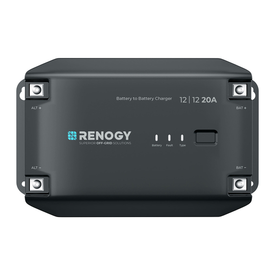
Page 16: Led Indicators
LED Indicators The battery charger turns on automatically after power on with the LED indicators working in accordance with the relative operating status. Battery Status Indicator Battery Type Indicator The battery charger is in Solid: SLD/AGM Solid: standby mode*, or the auxiliary Solid: battery is fully charged. -
Page 17: Configuration
Configuration 6.1. Set a Battery Type Renogy 12V 20A/40A DC-DC Battery Charger provides one easy-to-use button for setting the auxiliary battery type in your solar system. Upon installing the battery charger, set a correct battery type for the connected auxiliary battery either by using the Battery Type Setting Button or in the DC Home app. -
Page 18: Configure Charging Parameters
For how to adjust charging parameters for batteries in User Mode, refer to “6.3. Configure Charging Parameters” in this manual for details. Item RBC20D1U RBC40D1U Maximum Combined Maximum at 20A. Adjustable at 20A Maximum at 40A. Adjustable at Charging Current and 10A. - Page 19 5 seconds, the charger re-enters the Boost Charging phase from the Float Charge phase. █ Set Charging Current Setting the charging current for the battery charger is allowed in the DC Home app. Item RBC20D1U RBC40D1U Maximum at 20A. Adjustable at Maximum at 40A. Adjustable at 40A, 30A, 20A, Charging Current 20A and 10A.
-
Page 20: Activate Lithium Batteries
6.4. Activate Lithium Batteries The battery charger can activate connected lithium batteries. Lithium batteries may enter sleep mode when the built-in protection is triggered. In such case, the battery charger provides a small current to reactivate the sleeping lithium battery. The lithium battery can be charged normally after successful activation. -
Page 21: Monitoring
Accessories marked with “*” are available on renogy.com. Before adding this product to the DC Home app or Renogy ONE, please ensure that both the app version and the firmware version of Renogy ONE have been updated to the latest version. -
Page 22: Short-Range Monitoring
7.2. Wireless Long-Range Monitoring If long-range communication and programming are required, connect the battery charger to Renogy ONE Core (sold separately) through Bluetooth, and then pair Renogy ONE Core with the DC Home app. Required Components and Installation Instructions *RENOGY ONE Core Components marked with “*”... - Page 23 Step 1: Connect the battery charger to Renogy ONE Core through the Bluetooth of your phone. Step 2: Pair the Renogy ONE Core with the DC Home app through Wi-Fi or by scanning the QR code in the Renogy ONE Core. On Renogy ONE Core, go to “System > Settings > Pair with App” to get the QR code.
-
Page 24: Working & Charging Logic
Working & Charging Logic 8.1. Working Logic Renogy 12V 20A/40A DC-DC Battery Charger begins to charge the auxiliary battery based on the actual voltage of the starter battery as well as the DC alternator type. z Traditional DC Alternator (IGN connection not required): The starter battery begins charging the auxiliary battery when its voltage reaches 13.5V and stops charging when the voltage drops to 11.5V. - Page 25 █ Float Charge Stage During this stage the battery charger will supply a constant voltage which is determined by the battery selected and will keep current at a minimum level. This stage acts as a trickle charger. After reaching a constant voltage in the charging process, the battery charger reduces the voltage to a float level.
-
Page 26: Troubleshooting
If the multimeter beeps in continuity mode or shows a very low resistance value, there may be a short circuit inside the battery. Replace the battery or contact the battery manufacturer for help. 3. Reconnect them together safely. For technical support, contact our technical service through renogy.com/contact-us. — 22 —... -
Page 27: Built-In Protection Mechanisms
9.2. Built-in Protection Mechanisms The battery charger provides multiple protection mechanisms at the input terminal, output terminal, and battery charger sides. Protected Protection Description Remarks Device Mechanism This shirt-circuit protection is NOT applicable to a short- The battery charger will not work or be circuit within a starter battery. - Page 28 Mechanism The battery charger provides Output Side maximum constant charge current Overcurrent (Auxiliary (20A for RBC20D1U and 40A for Protection Battery) RBC40D1U) for the connected auxiliary battery. z -13°F to 113°F (-25°C to 45°C): The battery charger works at full load;...
-
Page 29: Dimensions & Specifications
10. Dimensions & Specifications 10.1. Dimensions █ 20A DC-DC Battery Charger (RBC20D1U) 1.59 in (40.5 mm) 5.17 in (131.5 mm) 8.56 in (217.5 mm) 9.31 in (236.5 mm) Dimension tolerance: ±0.2 in (0.5 mm) █ 40A DC-DC Battery Charger (RBC40D1U) 1.59 in... - Page 30 Parameter Name RBC20D1U RBC40D1U Communication Bluetooth Auxiliary battery: Overvoltage, overdischarge shutdown, Protection Mechanisms overtemperature, and short-circuit protection; Starter battery: Reverse contact and short-circuit protection Operating Temperature 32°F to 140°F (-25°C to 60°C) < 45°C: Full load; Derating > 45°C: Non-full load;...
-
Page 31: Maintenance
11. Maintenance 11.1. Inspection For optimum performance, it is recommended to perform these tasks regularly. z Ensure the battery charger is installed in a clean, dry, and ventilated area. z Ensure there is no damage or wear on the cables. z Ensure the firmness of the connectors and check if there are any loose, damaged or burnt connections. -
Page 32: Emergency Responses
2. Make sure no foreign objects are stuck in the fan of the battery charger or the ring terminal. The normal noise value of the battery charger is less than 40 dB during operation. If the noise is abnormal, contact our technical service through renogy.com/contact-us. — 28 —... -
Page 33: Renogy Support
Questionnaire Investigation To explore more possibilities of solar systems, visit Renogy Learning Center at: renogy.com/learning-center For technical questions about your product in the U.S., contact the Renogy technical support team through: renogy.com/contact-us 1(909)2877111 For technical support outside the U.S., visit the local website below: Canada ca.renogy.com... -
Page 34: Fcc Radiation Exposure Statement
FCC Statement This device complies with Part 15 of the FCC Rules. Operation is subject to the following two conditions: (1) This device may not cause harmful interference. (2) This device must accept any interference received, including interference that may cause undesired operation. - Page 35 Save 105 gallons of water from being consumed Renogy Power PLUS Renogy Power Plus allows you to stay in the loop with upcoming solar energy innovations, share your experiences with your solar energy journey, and connect with like-minded people who are changing the world in the Renogy Power Plus community.
Need help?
Do you have a question about the RBC20D1U and is the answer not in the manual?
Questions and answers