
Related Manuals for Renogy RBC2125DS-21W


Summary of Contents for Renogy RBC2125DS-21W
- Page 1 Renogy Dual Input DC-DC On-Board with MPPT Battery Charger 12V/24V 50A IP67 VERSION A0 RBC2125DS-21W January 16, 2024 QUICK GUIDE...
- Page 2 Before Getting Started The quick guide provides important operation and maintenance instructions for Renogy 12V/24V 50A IP67 Dual Input DC-DC On-Board with MPPT Battery Charger (hereinafter referred to as battery charger). Read the quick guide carefully before operation and save it for future reference. Failure to observe the instructions or precautions in the quick guide can result in electrical shock, serious injury, or death, or can damage the battery charger, potentially rendering it inoperable.
-
Page 3: Table Of Contents
Table of Contents What’s In the Box?..........................1 Dimensions ............................2 Get to Know Renogy Battery Charger ...................3 System Setup ...........................5 Recommended Tools & Accessories ....................6 Howto Size Wires? ..........................8 How to Install 15/32 in Lugs or 3/8 in Lugs? ................9 How to Install Cables on the Battery Charger? ................ - Page 4 USER Mode ............................. 25 Monitor the Battery Charger ....................... 26 Short-Range Monitoring via DC Home App ..................27 Wireless Long-Range Monitoring ....................28 Important Safety Instructions ....................29 Renogy Support ..........................31 FCC Statement ..........................33 FCC Radiation Exposure Statement ................... 34 Disclaimer ............................34...
-
Page 5: What's In The Box
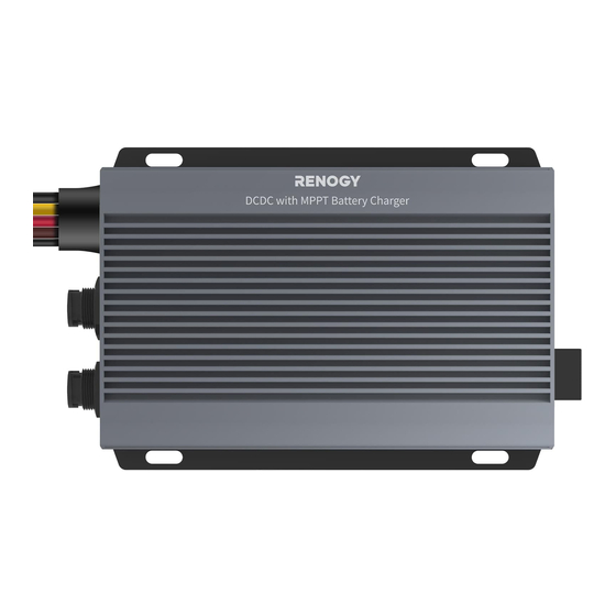
What’s In the Box? Renogy 12V/24V 50A IP67 Renogy Dual Input DC-DC On-Board Dual Input DC-DC On-Board with MPPT Battery Charger ST4*20 mm 12V/24V 50A IP67 VERSION A0 RBC2125DS-21W January 16, 2024 with MPPT Battery Charger × 1 QUICK GUIDE Quick Guide ×... -
Page 6: Dimensions
Dimensions 12 in (305 mm) 4.84 in (123 mm) 4.06 in (103 mm) 1.46 in (37 mm) 0.2 in (5 mm) 4.72 in (120 mm) 6.5 in (165 mm) 7 in (178 mm) Dimension tolerance: ±0.2 in (0.5 mm) — 2 —... -
Page 7: Get To Know Renogy Battery Charger
Get to Know Renogy Battery Charger Bluetooth Antenna Battery Type Setting Button Battery Type Indicator Solar Charging Indicator Auxiliary Battery Indicator Alternator Charging Indicator — 3 —... - Page 8 CAN Communication Ports Negative Common Cable (black) The battery temperature sensor cable can only be used with lead-acid batteries. For CAN Communication Ports wiring details, refer to the user manual of the battery charger at https:/ /www.renogy.com/support/downloads. — 4 —...
-
Page 9: System Setup
System Setup Positive Temperature Negative Communication Solar Panel (s) Auxiliary Battery (12V / 24V) Starter Battery DC-DC Battery Charger RV-C or Renogy devices supporting CAN communication — 5 —... -
Page 10: Recommended Tools & Accessories
Recommended Tools & Accessories Phillips Screwdriver (#1) Insulating Gloves Wire stripper Insulation Tape Heat Gun Heat Shrink Tubing Measuring Tape Manual Hydraulic Pliers — 6 —... - Page 11 Bare Wires Butt-Splices Busbar (60A to 100A) 3/8 in Lugs (M10 Ring Terminals) Prior to installing and configuring the battery charger, prepare the recommended tools, components, and accessories. The 3/8-inch lugs (M10 ring terminals) are used to connect the busbar and ANL fuse. For how to size bare wires, refer to “How to Size Wires?”...
-
Page 12: Howto Size Wires
Howto Size Wires? Select proper bare wires based on the cable length in your power system. Refer to the table below for recommended gauge sizes. Cable Cable Length Cable Gauge Size 0 ft to 10 ft (0 m to 3 m) 10 AWG (5.25 mm²) Output (to Auxiliary Battery) -
Page 13: How To Install 15/32 In Lugs Or 3/8 In Lugs
How to Install 15/32 in Lugs or 3/8 in Lugs? 0.4 in Heat (10 mm) Shrink Tubing — 9 —... - Page 14 — 10 —...
-
Page 15: How To Install Cables On The Battery Charger
How to Install Cables on the Battery Charger? █ Positive Cable The illustrations are based on the Positive Auxiliary Battery Cable. The butt-splice connectors we use in the manual come in separate butt-splices and heat shrink tubings. Heat Shrink Tubing Battery Bare Charger... - Page 16 █ Negative Cable For the negative terminals, we recommend a busbar. Install the 3/8-inch lugs (M10 ring terminals) on the solar panel, auxiliary battery, starter battery negative cables, and battery charger negative common cable (black) on the busbar. Solar Panel (s) 15/32 in Lug (M12 Ring Terminal)
-
Page 17: Step 1. Plan A Mounting Site
Step 1. Plan a Mounting Site The battery charger requires adequate clearance for installation, wiring, and ventilation. The minimum clearance is provided below. 5.91 in (150 mm) 5.91 in 5.91 in (150 mm) (150 mm) 5.91 in (150 mm) -31°F to 176°F 0% to 95% -35°C to 80°C FRAGILE... -
Page 18: Step 2. Connect The Battery Charger To A Busbar
Step 2. Connect the Battery Charger to a Busbar Negative Common Cable (black) 3/8 in Lug (M10 Ring Terminal) Busbar (60A to 100A) — 14 —... -
Page 19: Step 3. Connect The Battery Charger To An Auxiliary Battery
*12V/24V Battery (11V to 32V) *ANL Fuse (60A) × 1 Components and accessories marked with “*” are available on renogy.com. For installation details, see the user manual of the battery in use. Always connect the battery charger to a battery before connecting it to a solar panel to ensure safe and efficient operation. - Page 20 STEP-1 Install cables on the battery charger Positive Auxiliary Positive Cable Battery Cable (brown) of the Battery Charger (red bare wire) STEP-2 Install an ANL fuse 3/8 in Lug ANL Fuse (60A) 3/8 in Lug STEP-3 Install the cables on the battery 15/32 in Lug Auxiliary Battery —...
-
Page 21: Step 4. Connect The Battery Charger To A Solar Panel
*Solar Panel (s) *Solar Panel Fuse *Solar Panel Extension Cables Components and accessories marked with “*” are available on renogy.com. Connecting the battery charger to a solar panel exceeding 720W (≤50V) results in damage to the battery charger. The appropriate current rating for the solar panel fuse should be determined by multiplying the total short current amperage of the solar panel array by 1.56. - Page 22 STEP-1 Install cables on the battery charger Positive Solar Cable (yellow) Solar Panel of the Battery Charger Extension Cable STEP-2 Install a solar panel fuse Solar Panel Extension Solar Panel Extension Cable Solar Panel Fuse Cables Solar Panel Fuse STEP-3 Install the cables on the solar panel Solar Panel (s) —...
-
Page 23: Step 5. Connect The Battery Charger To A Starter Battery
12.7V for 12V systems or 25.4V for 24V systems. Recommended Accessories *ANL Fuse (70A) × 1 Accessories marked with “*” are available on renogy.com. The starter battery stops charging the auxiliary battery when the starter battery voltage drops below 12.7V for 12V systems or 25.4V for 24V systems. - Page 24 STEP-1 Install cables on the battery charger Positive Starter Positive Cable Battery Cable (red) of the Battery Charger (red bare wire) STEP-2 Install an ANL fuse 3/8 in Lug ANL Fuse (70A) 3/8 in Lug STEP-3 Install the cables on the RV starter battery 15/32 in Lug Starter Battery —...
-
Page 25: Step 6. Install A Battery Temperature Sensor
Step 6. Install a Battery Temperature Sensor The temperature sensor measures the surrounding temperature of the battery and compensates the floating charge voltage when the battery temperature is low. Do not use the temperature sensor on a LiFePO4 (LFP) battery which comes with a battery management system (BMS). -
Page 26: Led Indicators
LED Indicators The battery charger turns on automatically after power on with the LED indicators working in accordance with the relative operating status. Solar Charging Indicator Battery Type Indicator Off: Not charging Solid: Solid: Solid: MPPT charging Slow flash: Boost charging Solid: SLD/AGM Single flash:... - Page 27 Check out the graphic indications of ON, OFF, Solid, Slow Flash, Fast Flash, Single Flash, and Double Flash of LEDs in the table below: LED ON LED ON LED Pattern Graphic Expression Solid Slow Flash 0.1s 0.1s Fast Flash 0.2s 0.05s 1.95s Single Flash...
-
Page 28: Set A Battery Type
Set a Battery Type Upon installing the battery charger, set a correct battery type by using the Battery Type Setting Button. For non-lithium batteries, the battery charger can automatically detect their voltage (12V or 24V). It is essential to ensure that the battery type setting is configured correctly to avoid any potential damage to the battery charger because any damage to the battery charger resulting from an incorrect battery type setting voids the warranty. -
Page 29: User Mode
DC Home app. When customizing settings, consult the user manual provided by the battery manufacturer. If necessary, contact the manufacturer for further assistance. For detailed parameter settings, see the user manual of the battery charger at renogy. com/support/downloads. — 25 —... -
Page 30: Monitor The Battery Charger
To ensure optimal system performance, keep the phone or RENOGY ONE within 10 feet (3 m) of the battery charger. You can receive fault alarms on DC Home and Renogy ONE when the battery charger is faulty. Please login to the DC Home app or Renogy ONE for troubleshooting details. -
Page 31: Short-Range Monitoring Via Dc Home App
Short-Range Monitoring via DC Home App Pair the battery charger with the DC Home app. Monitor and modify the parameters of the battery charger via the app. My Renogy My Renogy HUB Mode Searching for device Time remaining Please make sure: 1. -
Page 32: Wireless Long-Range Monitoring
Wireless Long-Range Monitoring Recommended Components *RENOGY ONE Core Internet My Renogy Devices Battery Controller RBT12400LFPL-... DC-DC Device Scene Community — 28 —... -
Page 33: Important Safety Instructions
Important Safety Instructions █ General z Wear proper protective equipment and use insulated tools during installation and operation. Do not wear jewelry or other metal objects when working on or around the battery charger. z Keep the battery charger out of the reach of children. z Do not dispose of the battery charger as household waste. - Page 34 █ Battery Charger Safety z Install the battery charger on a vertical surface - protected from direct sunlight, high temperatures, and water. Make sure there is good ventilation. z Keep the battery charger away from heating equipment. z Do not insert foreign objects into the battery charger. z Confirm the polarities of the devices before connection.
-
Page 35: Renogy Support
Renogy Support To discuss inaccuracies or omissions in this quick guide or user manual, visit or contact us at: renogy.com/support/downloads contentservice@renogy.com Questionnaire Investigation To explore more possibilities of solar systems, visit Renogy Learning Center at: renogy.com/learning-center — 31 —... - Page 36 For technical questions about your product in the U.S., contact the Renogy technical support team through: renogy.com/contact-us 1(909)2877111 For technical support outside the U.S., visit the local website below: Canada ca.renogy.com China www.renogy.cn Australia Japan au.renogy.com renogy.jp South Korea kr.renogy.com Germany de.renogy.com...
-
Page 37: Fcc Statement
FCC Statement This device complies with Part 15 of the FCC Rules. Operation is subject to the following two conditions: (1) This device may not cause harmful interference. (2) This device must accept any interference received, including interference that may cause undesired operation. -
Page 38: Fcc Radiation Exposure Statement
Renogy and its licensors. The quick guide may not be modified, reproduced, or copied, in whole or in part, without the prior written permissions of Renogy and its licensors. z The registered trademarks in the quick guide are the property of Renogy. The unauthorized use of the trademarks is strictly prohibited. - Page 39 The illustrations in the quick guide are for demonstration purposes only. Details may appear slightly different depending on product revision and market region. z Renogy reserves the right to change the information in the quick guide without notice. For the latest quick guide, visit renogy.com.
- Page 40 Renogy Power PLUS Renogy Power Plus allows you to stay in the loop with upcoming solar energy innovations, share your experiences with your solar energy journey, and connect with like-minded people who are changing the world in the Renogy Power Plus community.
Need help?
Do you have a question about the RBC2125DS-21W and is the answer not in the manual?
Questions and answers