Table of Contents
Advertisement
Quick Links
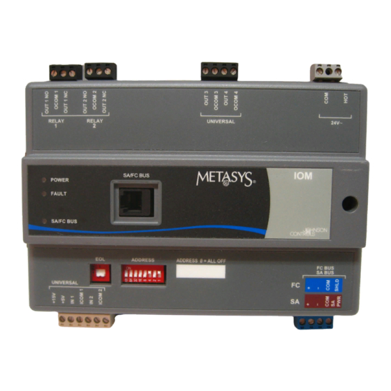
IOM2710 and IOM3710 Input/Output Modules
Installation Instructions
MS-IOM2710-0, MS-IOM3710-0
Applications
The Input/Output Module (IOM) 2710 and IOM3710 are
members of the Metasys® system Field Equipment
Controller (FEC) family. The IOM controller provides
increased capacity to larger FEC applications when
used on the Sensor-Actuator (SA) Bus. The IOM
controller can also be used on the Field Controller (FC)
Bus to connect additional I/O points to the system.
IMPORTANT: In Metasys system smoke control
applications, use only the IOM2710 and IOM3720
models that are UL Listed, UUKL 864 Listed, Smoke
Control Equipment. See Repair Information on page
8 for UUKL 864 Listed IOM2710 and IOM3710
models. For Metasys system smoke control
applications, you must refer to the Metasys System
UL 864 UUKL Ninth Edition Smoke Control System
Technical Bulletin (LIT-12011252) for detailed
requirements and procedures for installing and
operating UUKL 864 Listed Metasys system
devices. Failure to meet the requirements or follow
the procedures in the Metasys System UL 864
UUKL Ninth Edition Smoke Control System
Technical Bulletin (LIT-12011252) can void the
UUKL 864 listing for Smoke Control Equipment.
North American Emissions Compliance
United States
This equipment has been tested and found to
comply with the limits for a Class A digital device
pursuant to Part 15 of the FCC Rules. These limits
are designed to provide reasonable protection
against harmful interference when this equipment is
operated in a commercial environment. This
equipment generates, uses, and can radiate radio
frequency energy and, if not installed and used in
accordance with the instruction manual, may cause
harmful interference to radio communications.
Operation of this equipment in a residential area is
likely to cause harmful interference, in which case
the user will be required to correct the interference
at his/her own expense.
Canada
This Class (A) digital apparatus meets all the
requirements of the Canadian Interference-Causing
Equipment Regulations.
Cet appareil numérique de la Classe (A) respecte
toutes les exigences du Règlement sur le matériel
brouilleur du Canada.
Installation
Observe the following guidelines when installing the
IOM controller:
•
Transport the IOM controller in the original
container to minimize vibration and shock damage
to the IOM.
•
Do not drop the IOM controller or subject it to
physical shock.
Materials and Special Tools Needed
You need either of the following items to install the IOM
controller:
•
three fasteners appropriate for the mounting
surface (#8 screws or M4 screws)
•
one 20.3 cm (8 in.) or longer piece of DIN rail and
appropriate hardware for mounting the DIN rail
Mounting
Follow these guidelines when mounting an IOM
controller:
•
Ensure that the mounting surface can support the
IOM controller and any user-supplied enclosure.
•
Mount the IOM controller in the proper orientation.
See the Wall Mount Applications and DIN Rail
Mount Applications sections.
•
Mount the IOM controller on an even surface
whenever possible.
•
Use shims or washers to mount the unit securely
on the mounting surface.
•
Mount the IOM controller in areas free of corrosive
vapors and observe the environmental limitations
listed in the Technical Specifications section.
IOM2710 and IOM3710 Input/Output Modules Installation Instructions
Part No. 24-10144-17, Rev. G
Release 5.0
Issued January 4, 2010
Supersedes October 6, 2008
1
Advertisement
Table of Contents

Related Manuals for Johnson Controls IOM2710


Summary of Contents for Johnson Controls IOM2710
- Page 1 IOM controller: Control Equipment. See Repair Information on page • Transport the IOM controller in the original 8 for UUKL 864 Listed IOM2710 and IOM3710 container to minimize vibration and shock damage models. For Metasys system smoke control to the IOM.
-
Page 2: Wall Mount Applications
2. Mark the location of the wall mount holes using the Figure 3: Required Orientation for Wall Mount dimensions in Figure 3, or hold the IOM controller Applications up to the wall as a template and mark the locations. IOM2710 and IOM3710 Input/Output Modules Installation Instructions... -
Page 3: Din Rail Mount Applications
Mounting Clips (in Extended Positions) Figure 4: Required Orientation for DIN Rail Mount Applications Figure 2: IOM2710 and 3710 Controller Mounting Features, mm (in.) Wiring 3. Drill holes in the wall at the locations marked in Step 2 and insert wall anchors (if necessary). - Page 4 FEC, IOM, and VMA16 Stranded, 4-Wire (2 Twisted Pair) Shielded Cable (One twisted pair is the and leads. The second pair is COM and SA PWR.) Figure 6: SA Bus Terminal Block Wiring IOM2710 and IOM3710 Input/Output Modules Installation Instructions...
- Page 5 Table 1: IOM2710 and IOM3710 Controller Wiring List (Part 1 of 2) Terminal Terminal Function and Electrical Ratings/Requirements Wiring Requirements Labels (See Table 2 for A, B, or C.) Block Universal IN +5 V Sources 5 VDC power for active devices...
- Page 6 Table 1: IOM2710 and IOM3710 Controller Wiring List (Part 2 of 2) Terminal Terminal Function and Electrical Ratings/Requirements Wiring Requirements Labels (See Table 2 for A, B, or C.) Block Relay OUT NO n Normally Open Contact Output Connects OCOM to OUT NO when activated.
-
Page 7: Setup And Adjustments
IOM to the FC Bus or SA Bus. For more information, wireless operation. refer to the MS/TP Communications Bus Technical 129-255 Are not valid addresses for FEC or IOM Bulletin (LIT-12011034). controllers on the SA or FC Bus. IOM2710 and IOM3710 Input/Output Modules Installation Instructions... -
Page 8: Troubleshooting
8 in. Primary Leads and Secondary Screw Terminals, Class 2 AP-TBK1002-0 2-position Screw Terminal that Plugs onto VMA output point Spade Lugs AP-TBK1003-0 3-position Screw Terminal that Plugs onto VMA output point Spade Lugs IOM2710 and IOM3710 Input/Output Modules Installation Instructions... -
Page 9: Technical Specifications
On flat surface with screws on three mounting clips or a single 35 mm DIN rail Dimensions IOM2710: 180 x 127 x 58 mm (7-1/16 x 5 x 2-1/4 in.) (Height x Width x Depth) IOM 3710: 180 x 127 x 58 mm (7-1/16 x 5 x 2-1/4 in.) - Page 10 The performance specifications are nominal and conform to acceptable industry standard. For application at conditions beyond these specifications, consult the local Johnson Controls office. Johnson Controls, Inc. shall not be liable for damages resulting from misapplication or misuse of its products.
Need help?
Do you have a question about the IOM2710 and is the answer not in the manual?
Questions and answers