Table of Contents
Advertisement
Quick Links
Advertisement
Table of Contents

Related Manuals for Enerpac ERAK3000


Summary of Contents for Enerpac ERAK3000
- Page 1 Operation and Maintenance Manual Enerpac ERAK Reaction Arm Kit Document Number: L4640 Document Revision: D Document Revision Date: 14-NOV-2022 Document Language: English EN To reduce the risk of injury, users must read and understand this document before use.
-
Page 3: Warranty
& gas and power generation rely on Enerpac for quality tools, services and solutions. For additional information, visit www.enerpac.com. WARRANTY Refer to the Enerpac Global Warranty document for terms and conditions of the product warranty. Such warranty information can be found at www.enerpac.com. NAMEPLATE Tool Name... -
Page 4: Table Of Contents
Contents 1. SAFETY ........................3 1.1 SAFETY PRECAUTIONS .................. 3 2. FEATURES & COMPONENTS .................. 6 2.1 FEATURES DIAGRAM ..................6 3. TECHNICAL PRODUCT DATA ................. 7 3.1 DIMENSIONAL CALLOUT ART ................ 7 3.2 DIMENSIONAL TABLE ..................7 3.3 TORQUE TABLE ....................8 3.4 KIT, ADAPTOR, COMPONENTS WEIGHTS ............. -
Page 5: Safety
In situation that, if not avoided, could result in the event that any questions or concerns minor or moderate personal injury. arise, contact Enerpac or a local Enerpac NOTICE Indicates information distributor for clarification. - Page 6 • Do not place any objects between the • Never apply more hydraulic pressure wrench reaction foot and the reaction to any tool, hose, fitting or accessory point. Keep the hoses away from the than the maximum allowable pressure reaction points. stated manufacturer’s specifications.
- Page 7 Failure to • Never carry the wrench by its hoses. observe this precaution can result in the • Always use Enerpac pumps and hoses. wrench becoming unstable and can lead • Always use Enerpac replacement parts.
-
Page 8: Features & Components
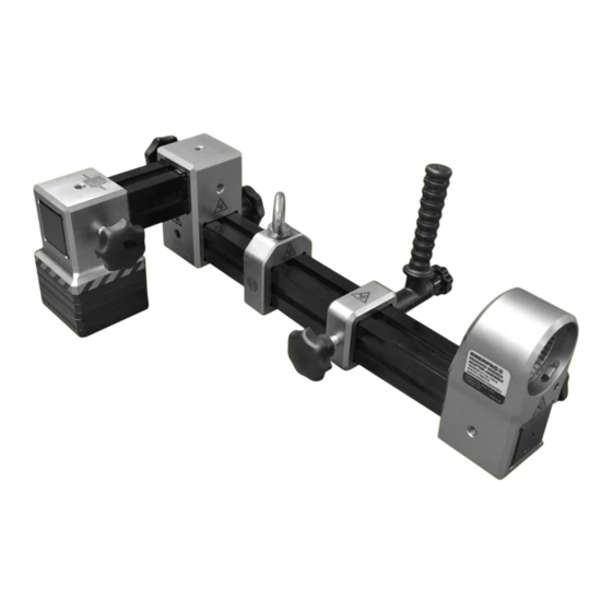
2. Features & Components 2.1 Features Diagram 1. Short Beam – 200mm [7.7/8"] 2. Long Beam – 450mm [17.5/8"] 3. Beam Connector Assembly, 90° 4. Lifting Point Assembly 5. Positioning Handle Assembly 6. Reaction Foot Assembly 7. Square Drive Adaptor Assembly RSL-Series Wrench S-Series Wrench Adaptor Assembly... -
Page 9: Technical Product Data
185-530 11.0 TWRAKRSL2-1500 RSL1500 [7.3-20.9] [5.8] [8.5] [4.5] [6.5] [24.2] 183-503 17.1 TWRAKS3 S3000X [7.2-19.8] [5.3] [8.2] [4.4] [6.9] [37.6] ERAK3000 222-542 17.1 TWRAKRSL4-3000 RSL3000 [8.7-21.3] [5.3] [8.2] [4.6] [6.9] [37.6] 270-552 36.2 TWRAKS6 S6000X [10.6-21.7] [4.6] [7.8] [6.1] [9.3] [79.6]... -
Page 10: Torque Table
Arm Kit Wrench* lb.ft lb.ft TWRAKS15 S1500X 1440 1952 ERAK1500 1500 2034 TWRAKRSL2-1500 RSL1500 1408 1909 TWRAKS3 S3000X 3225 4373 ERAK3000 3500 4745 TWRAKRSL4-3000 RSL3000 3080 4176 TWRAKS6 S6000X 6150 8338 ERAK8000 TWRAKRSL6-5000 RSL5000 5303 7190 8000 10847 TWRAKRSL8-8000 RSL8000... - Page 11 3.4.3 Component Weights Weight Weight (kg) (lb) Enerpac Reaction Arm Kit 1500 lb.ft / 2034 Nm Item ERAK1500 11.0 24.2 - S1500, RSL2, RSL1500 DM2140060 Beam-ERAK1500, 200mm / 7.7/8" Long DM2141060 Beam-ERAK1500, 450mm / 17.5/8" Long DM2142900 ERAK1500 Beam Connector Assembly, 90°...
-
Page 12: Operation
4. Operation 4.1 Mounting ERAK onto the Dialock wrenches 4.1.1 S-Wrench ERAK adaptor rotated incrementally through 360° maintain stability against a reaction point up to full torque. • Position the ERAK adaptor onto the splined end of the tool. • ERAK adaptor should be positioned parallel/perpendicular to the wrench. -
Page 13: Acceptable Assembly Orientations
4.3 Acceptable Assembly 4.2.1 Component Assembly/Locking Star Knob Orientations Once components are in desired position, Short/long beam assembled into tighten star knob to lock in place. adapter, with the reaction foot. Each component has multiple positions for • Reaction foot positioned the star knobs, use the position which will anywhere along the beam. -
Page 14: Unacceptable Assembly Orientations
Long beam into the adapter, short beam at 90°, with reaction foot. • 90° connector positioned anywhere along the beam. • Reaction foot positioned anywhere along the beam. Figure 9: Incorrect Reaction Foot Placement • ERAK Adaptor positioned on the short beam. -
Page 15: Manual Handling
4.5 Manual Handling • Although not necessary for lighter arrangements, it is advised to use the Refer section Kit, Adaptor, Lifting point assembly to assist handling Components Weights for detailed ERAK and positioning of the tool. tool weights. • Where possible, Lifting Point... -
Page 16: Parts List
6. Parts List 6.1 Exploded Views - ERAK1500, ERAK3000, ERAK8000 L4640_d... - Page 17 6.2 Table of Parts - ERAK1500, ERAK3000, ERAK8000 Part Numbers Item Description ERAK1500 Short Beam – 200mm [7.7/8"] DM2140060 Long Beam – 450mm [17.5/8"] DM2141060 Beam Connector Assembly, 90° DM2142900 Lifting Point Assembly DM2150900 Positioning Handle Assembly DM2152900 Reaction Foot Assembly...
- Page 18 6.3 View - RSL-Series Wrench 6.4 Table of Parts - RSL-Series Adaptor Assembly Wrench Adaptor Assembly Torque Wrench Part Numbers RSL1500 TWRAKRSL2-1500 RSL3000 TWRAKRSL4-3000 RSL5000 TWRAKRSL6-5000 RSL8000 TWRAKRSL8-8000 6.5 View - S-Series Wrench 6.6 Table of Parts - S-Series Adaptor Assembly Wrench Adaptor Assembly Torque Wrench Part Numbers...
- Page 19 Notes ____________________________________________________________ ____________________________________________________________ ____________________________________________________________ ____________________________________________________________ ____________________________________________________________ ____________________________________________________________ ____________________________________________________________ ____________________________________________________________ ____________________________________________________________ ____________________________________________________________ ____________________________________________________________ ____________________________________________________________ ____________________________________________________________ ____________________________________________________________ ____________________________________________________________ ____________________________________________________________...
- Page 20 © 2022 Enerpac Tool Group, All Rights Reserved. www.enerpac.com...
Need help?
Do you have a question about the ERAK3000 and is the answer not in the manual?
Questions and answers