Table of Contents
Advertisement
Quick Links
POWERFUL SOLUTIONS. GLOBAL FORCE.
L4256
Rev. C
Table of Contents:
1.0 IMPORTANT RECEIVING INSTRUCTIONS .................1
2.0 SAFETY .........................................................................1
INTERNATIONAL STANDARDS ....................................2
4.0 PRODUCT DESCRIPTION ...........................................3
5.0 HYDRAULIC SYSTEM ..................................................3
6.0 SETUP AND ASSEMBLY ..............................................4
7.0 INSTALLATION AND OPERATION ...............................4
8.0 INSPECTION, MAINTENANCE & STORAGE ............ 11
9.0 TROUBLESHOOTING ................................................ 11
10.0 CAPACITIES .............................................................13
11.0 PRODUCT DATA .......................................................14
1.0 IMPORTANT RECEIVING INSTRUCTIONS
Visually inspect all components for shipping damage. Shipping
damage is not covered by warranty. If shipping damage is
found, notify carrier at once. The carrier is responsible for
all repair and replacement costs resulting from damage in
shipment.
2.0 SAFETY
2.1 Introduction
Read all instructions carefully. Follow all recommended safety
precautions to avoid personal injury as well as damage to the
product and/or damage to other property. Enerpac cannot be
responsible for any damage or injury from unsafe use, lack of
maintenance or incorrect operation. Do not remove warning
labels, tags, or decals. In the event any questions or concerns
arise, contact Enerpac or your local Enerpac distributor for
clarification.
If you have never been trained on high force tool safety,
consult your distributor or service center for information about
an Enerpac Safety Course.
This manual follows a system of safety alert symbols, signal
words and safety messages to warn the user of specific
hazards. Failure to comply with these warnings could result
in death or serious personal injury, as well as damage to the
equipment or other property.
The Safety Alert Symbol appears throughout this
manual. It is used to alert you to potential physical
injury hazards. Pay close attention to Safety Alert
Symbols and obey all safety messages that follow this symbol
to avoid the possibility of death or serious personal injury.
Safety Alert Symbols are used in conjunction with certain
Signal Words that call attention to safety messages or
property damage messages and designate a degree or level
of hazard seriousness. The Signal Words used in this manual
are WARNING, CAUTION and NOTICE.
EN
11/19
Instruction Sheet
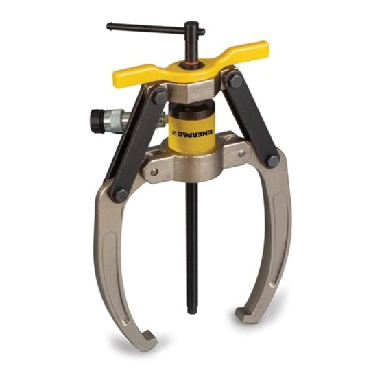
Hydraulic Lock Grip Pullers
LGH-Series
WARNING Indicates a hazardous situation that, if not
avoided, could result in death or serious
personal injury.
CAUTION Indicates a hazardous situation that, if not
avoided, could result in minor or moderate
personal injury.
Indicates information considered important,
NOTICE
but not hazard related (e.g. messages relating
to property damage). Please note that the
Safety Alert Symbol will not be used with this
signal word.
2.2 Safety Precautions - Hydraulic Lock Grip Pullers
Failure to observe and comply with the following
precautions could result in death or serious personal
injury. Property damage could also occur.
• Read and completely understand the safety precautions
and instructions in this manual before operating the puller or
preparing it for use.
• Wear appropriate personal protective equipment (PPE) such
as safety glasses and face shield. The operator must take
precautions against injury due to flying debris caused by
possible failure of the tool or workpiece.
• During operation, keep hands and fingers away from the
work area to avoid personal injury.
• Know the puller rated capacity before beginning any work.
• Do not use the puller in circumstances where a sudden
release of hydraulic pressure could result in loss of balance,
causing damage or injury.
• Never overload the puller or accessories. Never exceed
puller maximum capacities or maximum allowable hydraulic
working pressures. Refer to Sections 10.1 and 10.2 of this
manual for detailed puller capacity information and pressure
limits. Also observe and follow all operating precautions
communicated in Section 7.0 of this manual.
• Be aware that puller capacity will vary, depending on the
puller model, configuration and other variables.
1
WARNING
Advertisement
Table of Contents

Subscribe to Our Youtube Channel
Related Manuals for Enerpac LGH Series


Summary of Contents for Enerpac LGH Series
-
Page 1: Table Of Contents
Read all instructions carefully. Follow all recommended safety precautions to avoid personal injury as well as damage to the product and/or damage to other property. Enerpac cannot be Failure to observe and comply with the following responsible for any damage or injury from unsafe use, lack of precautions could result in death or serious personal maintenance or incorrect operation. -
Page 2: Conformance To National And International Standards
• Immediately replace worn or damaged parts with genuine [700 bar] working pressure. Enerpac parts. Enerpac parts are designed to fit properly and to withstand high loads. Non-Enerpac parts may break • The system operating pressure must not exceed the or cause the product to malfunction. -
Page 3: Product Description
4.3 Hydraulic Master Set (LGHMS-Series) 5.2 Hydraulic Cylinder The Enerpac Hydraulic Master Set includes all the items of the Hydraulic Set plus the following additional items: The hydraulic cylinder is pre-assembled in the body of the Lock Grip puller. -
Page 4: Setup And Assembly
Add oil if level is low. Refer to the pump instruction sheet for detailed instructions and oil type. Be sure to use a high quality hydraulic oil. Use of Enerpac oil is strongly recommended. 5.4 Advancing and Retracting the Cylinder •... - Page 5 If there are WARNING any questions or concerns, contact the Enerpac Technical Service Department or your local Enerpac distributor. Overloading and catastrophic failure could occur if the 1.
- Page 6 Ø B1 Ø B2 Ø B3 Example A Example B Example C Figure 7, Puller Maximum Reach and Spread Examples (three pulleys of different sizes) Example A Example B Example C Puller Model Number LGH210 / LGH310 3.94 11.81 5.71 9.84 8.07 7.87...
- Page 7 8. Support nut with the LGHS-Series Lock Grip Puller Set and the LGHMS-Series Master Puller Set. 9. Base screw Note: Refer to the document L4257 (www.enerpac. 10. Threaded base com) to find the suitable repair part kit for each 11. Hydraulic cylinder model of Hydraulic Lock Grip Puller.
- Page 8 (Assembled View) (Assembled View with extensions) Key: 1. Spindle 2. Threaded Saddle 3. Hydraulic Cylinder 4. Hex Nut 5. Washer 6. Slotted Crosshead 7. Leg Washer 8. Leg (various lengths) 9. Leg Reducer 10. Leg End 11. Mounting Screw Note: Components shown in this figure are included with the LGHMS-Series Master Puller Set.
- Page 9 (Assembled View - Cross Bearing Puller) (Assembled View - With Bearing Separator) Key: Note: Components shown in this figure are included in 1. Spindle 7. Leg Washer the LGHMS-Series Master Puller Set. 2.Threaded Saddle 8. Leg (various lengths) ( * ) See Section 11.7 for Legs specification. 3.
- Page 10 7.4 Cross Bearing Puller - Installation and Operation The cross bearing puller may be used independently by attaching the legs directly to the workpiece to be extracted (see Figure 11). In this case, the puller legs must be threaded directly into the workpiece (refer to Section 11.7 for thread specifications).
-
Page 11: Inspection, Maintenance & Storage
See Figure 15. • If the puller requires repairs, refer to the Enerpac website for • Read and understand the following warning statement the repair parts sheet applicable to your puller model. - Page 12 Troubleshooting Guide, LGH-Series Lock Grip Pullers Puller Mechanical Troubleshooting Symptom Possible Cause Solution 1. Jaws do not move Self-centering mechanism corroded or seized. Inspect self-centering mechanism. If corroded or seized, freely or are difficult to apply penetrating oil. Dismantle and clean mechanism move.
-
Page 13: Capacities
10.0 CAPACITIES 10.1 Maximum Rated Capacity Information-Pullers Maximum allowable Hydraulic hydraulic working Puller Quantity Puller Maximum Cylinder Maximum Cylinder pressure when cylinder Model of Jaws Rated Capacity Rated Capacity Model is installed on puller: Installed US Tons US Tons 91.7 LGH210 RWH101B100 10.3... -
Page 14: Product Data
11.0 PRODUCT DATA 11.1 Specifications and Dimensions - Puller Reach, Spread and Weights Ø B Capacity A max. Ø B max. Ø B min. Puller Model Tons 11.81 3.31 22.66 10.3 LGH210 10.3 91.7 8.46 7.56 LGH214 14.0 124.6 10.24 7.32 14.96 4.92... - Page 15 11.3 Specifications and Dimensions - Bearing Cup Puller Attachment S1, S2 S1 min. S2 max. Bearing Master Cup Puller Puller Set Attachment Model No. Model No. 3/4" UNF 16H BHP180 LGHMS310 1.57 5.71 5.31 9.29 4.40 3/4" UNF 16H BHP190 LGHMS314 1.57 5.71...
- Page 16 11.5 Specifications and Dimensions - Spindle and Point Protector Grip Puller Model No. LGH210 / LGH310 17.44 9.45 3/4” UNF 16h 0.59 0.79 0.63 LGH214 / LGH314 19.41 10.04 3/4” UNF 16h 0.83 1.50 0.65 16.5 LGH224 / LGH324 27.24 16.81 1”...
- Page 17 Notes:...
- Page 18 Notes:...
- Page 19 Notes:...
- Page 20 POWERFUL SOLUTIONS. GLOBAL FORCE. www.enerpac.com...
Need help?
Do you have a question about the LGH Series and is the answer not in the manual?
Questions and answers