Table of Contents
Advertisement
Quick Links
Operation and Maintenance Manual
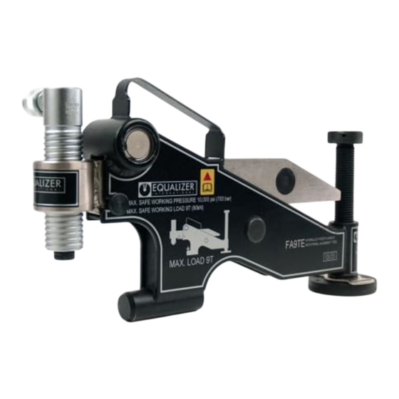
Enerpac FA1TMSTD (ATM2), FA4TMSTD (ATM4), FA9TESTD (ATM9)
Flange Alignment Tools
Document Number: L4769
Document Revision: C
Document Revision Date: 22-FEB-2024
Document Language: ENGLISH EN
To reduce the risk of injury, users must read and understand this document before use.
Advertisement
Table of Contents


Need help?
Do you have a question about the EQUALIZER FA1TMSTD and is the answer not in the manual?
Questions and answers