Advertisement
Table of Contents
- 1 Basic Information
- 2 Disclaimer of Warranties
- 3 Laser Safety Instructions
- 4 Electrical Safety Instructions
- 5 Installation Overview
- 6 Main Power Connection
- 7 Operation
- 8 Function Menu
- 9 Set Default Parameters
- 10 Diagnostic Tools
- 11 Maintenance Overview
- 12 Problems and Troubleshooting
- 13 Lubrication Instructions
- Download this manual
Technical Support and E-Warranty Certificate www.vevor.com/support
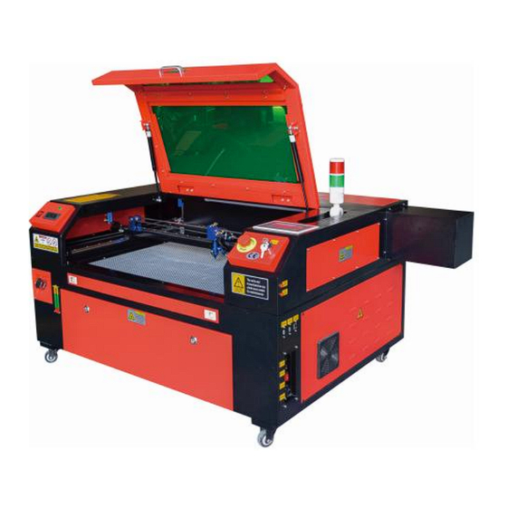
LASER ENGRAVING MACHINE
INSTRUCTION MANUAL
MODEL:KH5030/KH6040/KH7050/KH906/KH1490
KH-5030/KH-6040/KH-7050/KH-906/KH-1490
We continue to be committed to provide you tools with competitive price.
"Save Half", "Half Price" or any other similar expressions used by us only represents an
estimate of savings you might benefit from buying certain tools with us compared to the major
top brands and does not necessarily mean to cover all categories of tools offered by us. You
are kindly reminded to verify carefully when you are placing an order with us if you are
actually saving half in comparison with the top major brands.
Advertisement
Table of Contents

Related Manuals for VEVOR KH5030


Summary of Contents for VEVOR KH5030
- Page 1 Technical Support and E-Warranty Certificate www.vevor.com/support LASER ENGRAVING MACHINE INSTRUCTION MANUAL MODEL:KH5030/KH6040/KH7050/KH906/KH1490 KH-5030/KH-6040/KH-7050/KH-906/KH-1490 We continue to be committed to provide you tools with competitive price. "Save Half", "Half Price" or any other similar expressions used by us only represents an estimate of savings you might benefit from buying certain tools with us compared to the major top brands and does not necessarily mean to cover all categories of tools offered by us.
- Page 2 LASER ENGRAVING MACHINE MODEL:KH5030/KH6040/KH7050/KH9060/KH1490 KH-5030/KH-6040/KH-7050/KH-906/KH-1490 - 1 -...
- Page 3 This is the original instruction, please read all manual instructions carefully before operating. VEVOR reserves a clear interpretation of our user manual. The appearance of the product shall be subject to the product you received. Please forgive us that we won't inform you again if there are any technology or software updates on our product.
- Page 4 IMPORTANT NOTES CO2 laser engraver is suitable for both personal and professional use. When used in accordance with these instructions, it includes a Class 1 laser system, but some components are still very dangerous. Never disable pre-in-stalled safety equipment and always use the laser safely and responsibly.
- Page 5 jects in the equipment to prevent the laser from being reflected on the human body or flammable objects. During the operation of the equipment, the operator must always observe the operation of the equipment. If an abnormal situation occurs, please immediately. The equipment should be in a dry, pollution-free, vibration-free and strong electromagnetic interference environment, with a working temperature of 5-40 degrees Celsius and a humidity of 5-95%(non condensing water...
-
Page 6: Basic Information
BASIC INFORMATION This manual is a designated user guide engraver for cabinet laser installation, setup, safe operation, and maintenance. Covers general information, safety instructions, installation steps, operating instructions, maintenance procedures, and contact information. All personnel involved in the installation, setup, operation, maintenance, and repair of this machine should read and understand this manual, especially its safety instructions. - Page 7 should not be used with any lid open to avoid potential permanent injury. It should also be noted that both the cooling water system and the exhaust system are absolutely necessary for the safe use of this equipment. Do not operate the engraving machine without these two systems functioning properly.
- Page 8 The machine is suitable for engraving logos and other consumer products on applicable substrates. This laser can process a variety of materials, including wood and cork, paper and cardboard, most plastics, glass, cloth and leather, and stone. It can also be used with some specially coated metals.
- Page 9 Model KH5030 KH6040 KH7050 KH9060 KH1490 KH-5030 KH-6040 KH-7050 KH-9060 KH-1490 Input AC 120V AC 120V AC 120V AC 120V AC 120V voltage AC 230V AC 230V AC 230V AC 230V AC 230V Total power 420W 560W 680W 830W 900W...
- Page 10 1.Schematic diagram of the part. - 9 -...
- Page 11 2.Part Description. Viewing window: This tan acrylic window allows you to monitor the engraving process, but only partially absorbs the high infrared laser and has no other protection. Always wear glasses when using the Protective Observation Active Laser and never stare at it for long periods of time. LED Light: This light green light illuminates the workbench for a clear view of the material engraving before, during, and after work.
- Page 12 suffering from the laser beam and its reflections. This is also where the accessory bag was when the engraver first arrived. Front Access Door: This door provides access to the area below the bench for easy cleaning. Canopy: The lid provides access to the main bracket for placing and retrieving materials, as well as fixing laser path alignment and other maintenance.
- Page 13 check if this switch is off. Power Input: This power connector must be connected before using the machine. Top Rear Access Door: This door leads to the laser bay where the laser tube and its connections are secured. Rear Door: This door is the equivalent of a front door and requires similar care during use.
- Page 14 E. Focusing Lens:This lens directs and focuses the laser light onto the material. F. Workbench:The height of the exposed workbench can be adjusted. 4.Connect the inputs. A. USB Line Port:This port uses any of its USB ports to connect to the control com-puter and its engraving software.
- Page 15 5.Laser head assembly. A. Laser Head Third Mirror: This angle-adjustable mirror transmits laser light from the second mirror to the focusing lens. B. X-axis guide: This guide moves along the Y-axis, and its movement is controlled by a limit switch. C.
- Page 16 6.Right access door. A.Motherboard:This board controls the engraving process and responds to com-mands from the engraving software or the machine's control panel. B.X-axis driver: This device moves the laser head along the X-rail. C.Y-axis drive: This device moves the X-rail along the Y-rail. D.Laser Power: This device converts standard electricity into the extremely high voltage charge required for a laser tube.
- Page 17 8.Control the display. Button description - 16 -...
- Page 18 Display description A. Graphical display area: Displays the track and running track of the entire file. B. Version Number: Displays the version number of the panel and motherboard. C. System Time: Displays the current system time. D. Parameter display area: display the file number, speed, maximum power, etc.
-
Page 19: Disclaimer Of Warranties
I. System Status: Displays the current status of the machine: idle, running, paused, or completed. The processing time is shown on the right. J. Processing Progress Bar: Displays the progress of the current file. Note: When the system is idle or when the work is complete, all buttons are used. - Page 20 If any of these tags are missing, illegible, or damaged, they must be Replaced. Use this laser engraving device only in accordance with all applicable local and national laws and regulations. Use this appliance only in accordance with this instruction manual. Only others who have read and understood this manual are allowed to install, operate, maintain, repair, etc.
-
Page 21: Laser Safety Instructions
3.LASER SAFETY INSTRUCTIONS. When used as directed, the machine includes a Class 1 laser system that is safe for both users and bystanders. However, invisible lasers, laser tubes, and their electrical connections are still very dangerous. They can cause serious property damage and personal injury if not used or modified with care, including but not limited to the following: ... - Page 22 closure does not occur, do not continue to use it. Turn off the device and contact customer service or repair service. Never disable these closures. If the water cooling system is not working properly, do not use this laser engraver under any circumstances. Always activate the water cooling system and visually confirm that the water is flowing through the entire system before turning on the laser tube.
-
Page 23: Electrical Safety Instructions
4.ELECTRICAL SAFETY INSTRUCTIONS. Use this device only with a compatible and stable power supply with a voltage fluctuation of less than 10%. Do not connect other devices to the same fuse as the laser system requires its full amperage. Do not use with standard extension cords or power strips. - Page 24 5.MATERIAL SAFETY INSTRUCTIONS. It is the responsibility of the user of this laser engraving machine to confirm that the material to be processed is able to withstand the heat of the laser and does not produce any emissions or by-products that are harmful to nearby people or that violate local or national laws or regulations.
- Page 25 This machine is safe to use with the following materials: 1.plastics. ·Acrylonitrile butadiene styrene (ABS) ·Nylon (polyamide, PA, etc.) ·polyethylene ·High-density polyethylene (high-density polyethylene, polyethylene, etc.) ·Biaxially oriented polyethylene terephthalate (BoPET, polyester, polyester, etc.) ·Polyethylene terephthalate (PETG, PET-G, etc.) ·Polyimide (PI, Kapton, etc.) ·Polymethyl methacrylate (PMMA, acrylic, plexiglass, fluorite, etc.) ·Polyoxymethylene (POM, acetal, DL, etc.) ·Polypropylene (PP, etc.)
- Page 26 This unit cannot be used with the following materials or any materials containing them: · Artificial leather containing hexavalent chromium (Cr[VI]) due to its toxic fumes ·Astatine due to its toxic fumes ·Beryllium oxide, due to its toxic fumes ·Bromine, due to its toxic fumes ·Chlorine, including polyvinyl butyral (PVB) and polyvinyl chloride (PVC, vinyl, Sintra, etc.), due to its toxic fumes ·Fluorine, including Teflon (Teflon, Teflon, etc.), due to its toxic fumes...
-
Page 27: Installation Overview
INSTALLATION 1.INSTALLATION OVERVIEW. A complete working system includes the laser engraving cabinet, its vents, all applicable connection cables, as well as the laser and access key. The cabinet can use the design provided by the included engraving software by connecting directly with your computer or the internet; It can also engrave designs that are loaded directly from flash drives. - Page 28 Depending on the material to be processed, this may require the construction of a dedicated ventilation system. It should be kept away from children; flammable, flammable, explosive or corrosive materials; and sensitive EMI equipment. The power cord should be plugged into a compatible and stable power source through a grounded 3-pin outlet.
- Page 29 4. UNPACK THE ENGRAVING MACHINE. Your engraver comes in a wooden case with its accessories (including this manual) packed in the area behind the front through door. You should place the crate in a generous, flat area for unpacking, and ideally, you plan to operate the machine permanently.
-
Page 30: Main Power Connection
5.MAIN POWER CONNECTION. Confirm that the label next to the connected outlet on the machine matches your power supply. Connect one end of the main cable to a connection socket and the other end to a grounding socket. Under no circumstances should you turn on the device if the voltage does not correspond. - Page 31 Please rotate to remove the dust cover of the water inlet, and then add purified water or distilled water to the water inlet for the engraving machine. The green range of the water level line is the safe water level, and then you can fill the water nozzle dust cover, and then turn on the main power supply and water circulation switch of the machine.
- Page 32 7.INITIAL TESTING. EMERGENCY SHUTDOWN. Due to the risk of fire and other hazards during the engraving process, the engraving machine includes a large, easy-to-reach emergency stop button near the control panel. Press it to stop the laser tube immediately. When your engraver arrives, its emergency stop has been pressed and must be rotated to the right and bounce upwards for the laser to work.
- Page 33 WATER CUT-OFF. Due to the dangers posed by uncooled laser tubes, the engraver also automatically shuts down the laser when the water cooling system fails. After making sure that both the emergency stop button and the lid protection are working properly, you should also test that the water cut-off is working properly before doing any other work on the machine.
- Page 34 AIR ASSISTED. Your air auxiliary equipment should be pre-installed and properly wired. Just check if it is properly configured and connected as shown in the image. If any pipes or wiring need to be reconnected, turn off all power to the machine (including pressing the emergency stop) before adjusting any equipment.
-
Page 35: Operation
OPERATION 1.OPERATION OVERVIEW. Operate this laser engraver only by following all the instructions provided in this manual. Failure to follow the appropriate guidelines detailed herein may result in property damage and personal injury. This section will describe only some of the options and features offered by the operating software. - Page 36 Step 5. Open the engraver cover, check that the air assist is working properly, and adjust the table if necessary. Cellular beds are recommended for most applications. The bed can be raised or lowered using the Z-axis control on the front of the cabinet to accommodate a variety of materials of different thicknesses.
- Page 37 The minimum threshold is 10%. The laser will not be emitted at any setting lower than this setting. It is not recommended to use the laser tube at full load, especially for long periods of time. The recommended maximum power is set at 70%, as prolonged use of more than this amount will shorten the lifetime of the laser.
- Page 38 Step 12. When you are done engraving, close the engraving software and turn off the machine in the following order: laser power, control panel, any ventilation, water cooling system, and emergency power button. Remove the laser key from the control panel. Step 13.
- Page 39 TEXTILES. When it comes to carving textiles such as cloth and wool, low power and high speed are often used. As with leather, special attention should be paid to the possibility of fire and dust. GLASS. When engraving glass, high power and low speed are generally used. As with ceramic, it would be helpful to run more cycles on a lower setting to avoid cracks.
- Page 40 PLASTICS. The plastic used for engraving comes in many different colors and thicknesses and has many different coatings and finishes. Most of the plastics available can be engraved and cut well with lasers. Plastics with microporous surfaces seem to provide the best results because less surface material needs to be removed. When engraving plastics, low-power, high-speed settings are generally used.
- Page 41 TIMBER. As with rubber, there are many different types of wood, and testing your specific material is essential to get the best results. In general, wood carvings with consistent grain and color are more uniform. Knotted wood creates an uneven effect, while resin wood creates greater edge contrast.
- Page 42 Refer to Usage Data. IT IS RECOMMENDED TO SET THE POWER TO 80 100W 130W 150W materi thickne Faste Optim Faste Optim Faste Optim Faste Optim Fastes Optim Faste Optim speed speed speed speed speed speed speed speed speed speed speed speed 15/S...
- Page 43 4.CONSOLE DESCRIPTION. OVERVIEW. You can control the engraver directly from the built-in control panel, directly connected to a computer, or via the Internet. For more information on operating the engraving software, please refer to its separate manual. The built-in control panel allows the laser to be operated manually, or the design can be engraved onto flash drives and external hard drives connected to the USB port on the right side of the cabinet.
- Page 44 To load a design from a FAT16 or FAT32 formatted flash drive or external hard drive, press MENU, select "File", then "Udisk+", and then "Copy to Memory". Select the design in the File menu, and then select Run. Various parameters can be adjusted using the console's menus and submenus, including setting multiple origins to engrave a design on a material four times in a single session.
- Page 45 Just like the button says, press Run/Pause to start engraving the loaded pattern and pause the engraving when needed. In the event of an emergency such as fire, do not use the control panel to pause or stop engraving. Press the emergency stop button immediately. SET THE LASER POWER.
- Page 46 Press ENT to save your changes. Press ESC to invalidate the changes and go back to the main interface. SET THE LASER SPEED When you press ENT in the main interface, the cursor box initially selects the "Speed" parameter. Press the ENT key again to bring up this interface. Press the ▲...
-
Page 47: Function Menu
FUNCTION MENU. Press the menu on the main interface to enter the menu interface: Press the ▲ and ▼ keys to select the item, and then press ENT to enter the corresponding submenu. ADJUST THE Z-AXIS. When Z Move is selected, press ◄ or ► to control the movement of the Z axis while the sensor kit is installed. - Page 48 RESET THE AXIS. When Shaft Reset+ is selected, press ENT, and the left display will show:Push ▲ or ▼ to select an item. Press ENT to start resetting the selected axis and the message "Reset in progress" will appear on the screen. When it is done, the message will disappear automatically and the system will return to the main interface.
- Page 49 ADJUST THE LASER MOVEMENT MODE. When you select Manual Settings, press ENT, and the left side will be displayed:When the movement mode is "Continuous", the manual jog parameter does not work. When used to manually move the laser head, the arrow keys move it continuously until released. When the movement mode is "Jog", each time the arrow keys are pressed, the laser head will move precisely the distance saved in this parameter.
-
Page 50: Set Default Parameters
when disabled, the small box will be gray. When you select Set Origin or Next Origin, press◄ or ► to select a value. When changing the Set Origin parameter, remember to press ENT to verify the change. When you close the interface, the parameters are automatically saved. The details of each item are as follows: ·Set Origin 1/2/3/4: After enabling the multi-origin setting, place the cursor over setting to Origin 1/2/3/4. - Page 51 SET THE INTERFACE LANGUAGE. When selecting a language, press ENT and the left display will show: The operation method is the same as above. Press ENT after selecting the desired language and return to the main interface. SET THE IP ADDRESS OF THE MACHINE. Once you have selected your IP settings, press ENT and the left display will show: Push ◄...
-
Page 52: Diagnostic Tools
Connecting the machine directly to the public internet carries the risk of unauthorized use and is not recommended. If you still wish to provide it, you'll need to register and use a unique public TCP/IP address. When you're done making adjustments, save them by selecting the ENT key to write or pressing the ESC key to leave without saving the changes. - Page 53 SETTING THE SCREEN REFERENCE. After selecting the Screen Origin, the left dialog box will pop up: This interface displays the location of the origin. Different origin positions can produce different reflections of the graph on the X/Y axis. The operation method is the same as above. ADJUSTING THE SCULPT LAYER.
- Page 54 ADJUST MOVEMENT PARAMETERS. In the Parameter Settings submenu, select Move Parameters to display the left interface:Select and adjust parameters by pressing the arrows. When you're done adjusting, move the cursor to Write and press ENT to save the parameter changes, or press ESC to exit without saving. Reading can load saved parameters.
- Page 55 SET BLOWING PARAMETERS. In the Paragraph Settings submenu, select Blow Settings to display the left interface:Select and adjust parameters by pressing the arrows. When you're done adjusting, move the cursor to Write and press ENT to save the parameter changes, or press ESC to exit without saving. Reading can load saved parameters.
- Page 56 ADJUST THE MACHINE CONFIGURATION. In the Parameter Settings submenu, select Computer Configuration to display the left interface: Select and adjust parameters by pressing the arrows. When you're done adjusting, move the cursor to Write and press ENT to save the parameter changes, or press ESC to exit without saving.
- Page 57 SET THE INTERFACE PASSWORD. When the cursor is on the panel lock, press ENT, and the left dialog box will pop up: Press the ▲ and ▼ keys to select the item. When the blue cursor is over the target item, press ENT to enter the corresponding interface. BACKUP AND RESTORE PARAMETERS.
- Page 58 SET THE DATE AND TIME OF THE MACHINE. In the Controller Settings submenu, select Time Settings+ to display the left interface: Select and adjust parameters by pressing the arrows. When you're done adjusting, move the cursor to Write and press ENT to save the parameter changes, or press ESC to exit without saving.
-
Page 59: Maintenance Overview
MAINTENANCE 1.MAINTENANCE OVERVIEW. Use of procedures other than those specified herein may result in dangerous exposure to laser radiation. Always turn off the appliance and disconnect it from the power supply before performing any cleaning or maintenance work. Always keep the system clean, as flammable debris in the work and exhaust areas poses a fire hazard. - Page 60 down or find a way to lower its temperature without interrupting the laser tube's water supply. The water should also not get too cold, which can also cause the glass laser tube to shatter during use. In the winter months or if using ice to cool hot water, make sure the temperature never drops below 50°F (10°C).
- Page 61 2. Move the laser head to the center of the table and place a cloth under the lens mount so that the lens will not be damaged if it accidentally falls off the mount. 3. Unscrew the lens mount and rotate it to the left. 4.
- Page 62 11. Repeat the same cleaning process on the other side of the lens. Never use cleaning paper towels twice. Dust that accumulates in cleaning paper towels may scratch the surface of the lens. 12. Check the lens. If it is still dirty, repeat the cleaning process above until the lens is clean.
- Page 63 touch the surface of the mirror directly. Avoid pressing too hard to grind any debris and cause scratches. If the mirrors are removed for cleaning, reinstall them by rotating them clockwise into place while being careful to avoid any scratches. 4.LASER PATH ALIGNMENT.
- Page 64 Perform beam alignment at low power levels: 15% or less. Any higher percentage will cause the laser to ignite the test strip instead of marking it. Make sure to set the maximum power (not the minimum) to 15%. LASER TUBE ALIGNMENT. To test the alignment of the laser tube with the first mirror, cut a strip of tape and place it on the frame of the mirror.
- Page 65 FIRST MIRROR ALIGNMENT. After ensuring that the laser light is properly aligned between the laser tube and the first mirror, check the alignment between the first mirror and the second mirror. First, use the directional arrows on the control panel to send the second mirror to the back of the bed along the Y axis.
- Page 66 To adjust the mirror, loosen the nut on the screw and gently turn the screw clockwise or counterclockwise. Each screw adjusts a different position or angle. Keep track of the screws you are adjusting and the direction of adjustment. Do not turn the screw more than 1/4 turn at a time, especially test the position of the laser after each adjustment so that you can see the effect of each replacement.
- Page 67 THIRD MIRROR ALIGNMENT. After ensuring that the laser is properly aligned between the 2nd and 3rd mirrors, check the alignment between the 3rd mirror and the table. First, remove the air assist hose from the laser head. Then, place a piece of tape on the bottom of the laser head and press it firmly against the nozzle.
-
Page 68: Problems And Troubleshooting
1. Please install it according to the logo on the laser, and correctly connect the cathode and anode connection wires, water inlet pipe and water outlet pipe of the laser. 2. Turn on the chiller and adjust the laser angle to ensure that the coolant is full of the laser and there is no clogging. -
Page 69: Lubrication Instructions
Problem 4: Requirements for the environment. ①The laser is equipped with a power supply and needs to operate in a well-ventilated environment. ②The workspace needs to meet local safety standards for the operation of laser equipment. Note:Environmental Requirements. Operating temperature: 10°C~38°C Storage temperature: -10°C~35°C Storage humidity: 20%RH~80%RH 5.LUBRICATION INSTRUCTIONS. - Page 70 DAILY TROUBLESHOOTING TABLE ISSUE CAUSE OF THE PROBLEM SOLUTION The door is not dosed Close the door The panel indicates that The cover protection switch is Replace with a new he machine is protected damaged The water pipes are clogged and Clean the water pipes there a no water circulation The panel indicates that...
- Page 71 1. Instructions *1 2. Smoke exhaust pipes *1 3. Double-sided tape *1 4. Clamps *1 5. Screwdriver *1 6. Allen key *1SET 7. Grounding wire *1 8. Power cord *1 9. Data cable *1 10. Crystal network cable *1 11. Document bag *1 12.
- Page 72 Technical Support and E-Warranty Certificate www.vevor.com/support...
Need help?
Do you have a question about the KH5030 and is the answer not in the manual?
Questions and answers