
Related Manuals for Schmalz SCPSb-UHV-HD


Summary of Contents for Schmalz SCPSb-UHV-HD
- Page 1 Operating instructions SCPSb-UHV-HD Compact Ejector WWW.SCHMALZ.COM EN-US · 30.30.01.02662 · 01 · 09/22...
- Page 2 Published by © J. Schmalz GmbH, 09/22 This document is protected by copyright. J. Schmalz GmbH retains the rights established thereby. Repro- duction of the contents, in full or in part, is only permitted within the limits of the legal provisions of copyright law. Any modifications to or abridgments of the document are prohibited without explicit writ- ten agreement from J. Schmalz GmbH.
-
Page 3: Table Of Contents
Contents Contents 1 Important Information ........................... 5 Note on Using this Document...................... 5 The technical documentation is part of the product ................ 5 Type Plate............................. 6 Symbol .............................. 6 2 Fundamental Safety Instructions........................ 7 Intended Use ............................ 7 Non-Intended Use.......................... 7 Personnel Qualifications........................ - Page 4 Contents 10.2 Cleaning the Ejector .......................... 22 10.3 Replacing the Press-In Screens ...................... 22 10.4 Replacing the Silencer Insert...................... 22 10.5 Cleaning or Changing the Nozzle..................... 23 11 Warranty ............................... 25 12 Spare and Wearing Parts, Accessories ...................... 26 12.1 Spare and Wearing Parts........................
-
Page 5: Important Information
ð Failure to follow the instructions in these Operating instructions may result in injuries! ð Schmalz is not liable for damage or malfunctions that result from failure to heed these instructions. If you still have questions after reading the technical documentation, contact Schmalz Service at: www.schmalz.com/services... -
Page 6: Type Plate
1 Important Information 1.3 Type Plate The type plates (1) and (2) are permanently at- tached to the product and must always be clearly legible. Type plate (1) contains the following information: • EAC label • Pneumatic symbol • Part sales designation/type •... -
Page 7: Fundamental Safety Instructions
Intended use includes observing the technical data and the installation and operating instructions in this manual. 2.2 Non-Intended Use Schmalz accepts no liability for damages caused by non-intended usage of the ejector. In particular, the following are considered non-intended use: •... -
Page 8: Residual Risks
4 Wear eye protection. 2.6 Modifications to the Ejector Schmalz assumes no liability for consequences of modifications over which it has no control: 1. The ejector must be operated only in its original condition as delivered. 2. Use only original spare parts from Schmalz. -
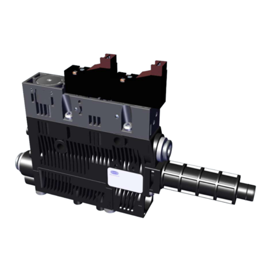
Page 9: Product Description
3 Product Description 3 Product Description 3.1 Ejector Designation The breakdown of the item designation (e.g. SCPSb-UHV-HD 16 S02 NO) is as follows: Property Variants Type of ejector SCPSb-UHV-HD (Ultra High Vacuum-Heavy Duty) Nozzle size 0.7 mm; 1.1 mm; 1.6 mm Connection S02 (plug-in screw unions for pneumatic hose: compressed air 6/4, vacuum... -
Page 10: Technical Data
4 Technical Data 4 Technical Data 4.1 General Parameters Parameter Symbol Limit value Unit Comment min. typ. max. Working temperature ° C Storage temperature ° C Humidity % r.h. Free from condensation Degree of protection IP40 Operating pressure (flow pressure) Operating medium Air or neutral gas, 5 µm filtered, with or without oil, class 3-3-3 com- pressed air quality in acc. -
Page 11: Dimensions
4 Technical Data 4.4 Dimensions 18.6 81.6 98.8 40.8 47.5 16.5 31.5 6 / 8 36.9 16.5 4.5 Pneumatic Circuit Plans SCPSb...NO... SCPSb...NC... EN-US · 30.30.01.02662 · 01 · 09/22 11 / 30... -
Page 12: General Description Of Functions
5 General Description of Functions 5 General Description of Functions 5.1 Applying Suction to the Workpiece/Part The ejector is designed for vacuum handling of airtight parts in combination with suction systems. The vacuum is generated in a nozzle according to the Venturi principle, using suction generated by the flow of accelerated compressed air. -
Page 13: Changing The Blow-Off Flow Rate On The Ejector
5 General Description of Functions 5.4 Changing the Blow-Off Flow Rate on the Ejector There is a valve screw below the vacuum connection that can be used to adjust the blow-off flow rate. The valve screw is equipped with a stop on both sides. Valve screw 1. -
Page 14: Transport And Storage
1. Compare the entire delivery with the supplied delivery notes to make sure nothing is missing. 2. Damage caused by defective packaging or occurring in transit must be reported immediately to the carrier and J. Schmalz GmbH. 14 / 30 EN-US · 30.30.01.02662 · 01 · 09/22... -
Page 15: Installation
7 Installation 7 Installation 7.1 Installation Instructions CAUTION Improper installation or maintenance Personal injury or damage to property 4 During installation and maintenance, make sure that the product is disconnected and depressurized and that it cannot be switched on again without authorization. For safe installation, the following instructions must be observed: •... -
Page 16: Pneumatic Connection
7 Installation 7.3 Pneumatic Connection CAUTION Compressed air or vacuum in direct contact with the eye Severe eye injury 4 Wear eye protection 4 Do not look into compressed air openings 4 Do not look into the silencer air stream 4 Do not look into vacuum openings, e.g. suction cups CAUTION Noise pollution due to incorrect installation of the pressure and vacuum connec- tions... - Page 17 7 Installation ü The corresponding pneumatic hose is handy. 4 The compressed air connection is marked with the number 1 on the ejector (Shown here in the image as an example.). The vacuum connection is marked with the number 2 on the ejector. Press the corresponding pneumatic hoses (compressed air supply and suction cup con- nection) as far as possible into the plug-in...
-
Page 18: Electrical Connection
7 Installation The following table shows the recommended line cross-sections (internal diameter): Performance class Line cross-section (internal diameter) in mm Pressure side Vacuum side SCPS(b,i) UHV HD 07 SCPS(b,i) UHV HD 11 SCPS(b,i) UHV HD 16 Based on a maximum hose length of 2 m. 4 For longer hose lengths, the cross-sections must also be larger. -
Page 19: Operation
8 Operation 8 Operation 8.1 Safety Instructions for Operation WARNING Suspended load Risk of serious injury 4 Do not walk, stand or work under suspended loads. WARNING Change of output signals when product is switched on or plug is connected Risk of injury to persons and damage to property due to uncontrolled movements of the higher-level machine/system! 4 The electrical connection must be performed only by specialists who can evaluate the effects of signal changes on the overall system. -
Page 20: General Preparations
8 Operation CAUTION When the system is started in automatic operation, components move without ad- vanced warning. Risk of injury 4 Ensure that the danger zone of the machine or system is free of persons during auto- matic operation. 8.2 General Preparations Always carry out the following tasks before activating the system: 1. -
Page 21: Troubleshooting
9 Troubleshooting 9 Troubleshooting 9.1 Help with Malfunctions Fault Possible cause Solution 4 Make sure device is properly con- Power supply disrupted Electrical connection nected to power 4 Check electrical connection Ejector does not re- No power supply spond 4 Check the compressed air supply No compressed air supply 4 Replace the silencer Vacuum level is not... -
Page 22: Maintenance
10 Maintenance 10 Maintenance 10.1 Safety Maintenance work may only be carried out by qualified personnel. WARNING Risk of injury due to incorrect maintenance or troubleshooting 4 Check the proper functioning of the product, especially the safety features, after every maintenance or troubleshooting operation. NOTE Incorrect maintenance work Damage to the ejector! -
Page 23: Cleaning Or Changing The Nozzle
10 Maintenance If the suction capacity decreases, replace the silencer insert: ü Deactivate the ejector and disconnect it from the supply lines. 1. Unlock the silencer cover by turning the bayo- net fastener 90°. 2. Remove the silencer cover. 3. Replace the silencer insert (1). 10.5 Cleaning or Changing the Nozzle The easy access to the silencer insert and nozzle provided by the silencer cover with bayonet fastener en- sures that the nozzle is easy to clean and replace. - Page 24 10 Maintenance ð The nozzle is removed together with the O-ring. 2. Check the nozzle and clean or replace it if nec- essary. 3. Install any cleaned or new nozzle in the cor- rect position. Ensure that the O-ring is fitted. O-Ring 24 / 30 EN-US ·...
-
Page 25: Warranty
11 Warranty 11 Warranty This system is guaranteed in accordance with our general terms of trade and delivery. The same applies to spare parts, provided that these are original parts supplied by us. We are not liable for any damage resulting from the use of non-original spare parts or accessories. The exclusive use of original spare parts is a prerequisite for the proper functioning of the ejector and for the validity of the warranty. -
Page 26: Spare And Wearing Parts, Accessories
12 Spare and Wearing Parts, Accessories 12 Spare and Wearing Parts, Accessories 12.1 Spare and Wearing Parts Maintenance work may only be carried out by qualified personnel. 4 WARNING! Risk of injury due to improper maintenance! After performing any maintenance or re- pair work, check that the system is functioning correctly, particularly the safety features. NOTE Incorrect maintenance work Damage to the ejector! -
Page 27: Decommissioning And Recycling
13 Decommissioning and Recycling 13 Decommissioning and Recycling 13.1 Disposing of the Product 1. Dispose of the product properly after replacement or decommissioning. 2. Observe the country-specific guidelines and legal obligations for waste prevention and disposal. 13.2 Materials Used Component Material Housing PA6-GF Inner components Aluminum alloy, anodized aluminum alloy, brass, galvanized steel, stainless- steel, PU, POM... -
Page 28: Declarations Of Conformity
14 Declarations of Conformity 14 Declarations of Conformity 14.1 EC Conformity EU Declaration of Conformity The manufacturer Schmalz confirms that the product Ejector described in these Operating instructions ful- fills the following applicable EU directives: 2014/30/EU Electromagnetic Compatibility 2011/65/EU RoHS Directive The following harmonized standards were applied: EN ISO 12100... - Page 29 EN-US · 30.30.01.02662 · 01 · 09/22 29 / 30...
- Page 30 At Your Service Worldwide Vacuum Automation Handling Systems WWW.SCHMALZ.COM/AUTOMATION WWW.SCHMALZ.COM/AUTOMATION J. Schmalz GmbH Johannes-Schmalz-Str. 1 72293 Glatten, Germany T: +49 (0) 7443 2403-0 schmalz@schmalz.de WWW.SCHMALZ.COM...
Need help?
Do you have a question about the SCPSb-UHV-HD and is the answer not in the manual?
Questions and answers