
Subscribe to Our Youtube Channel
Related Manuals for Smoke hollow 3100


Summary of Contents for Smoke hollow 3100
- Page 1 This Owner's Manual is provided and hosted by Appliance Factory Parts. Smoke Hollow 3100 Owner's Manual Shop genuine replacement parts for Smoke Hollow 3100 Find Your Smoke Hollow Grill Parts - Select From 115 Models -------- Manual continues below --------...
- Page 2 Grill 3100 Conforms to ANSI STD Z21.58b-2012 OUTDOOR COOKING GAS APPLIANCE DANGER 1. Never operate this appliance unat- tended. 2. Never operate this appliance within 10 ft (3.0 m) of any structure, com- bustible material or other gas cylin- der.
- Page 3 WARNING DANGER For Outdoor Use Only Never use the gas or charcoal grill ● (outside of any type of enclosure) for INDOOR cooking or heating Never use the grill on or in a boat or ● recreational vehicle The combustion fumes from either the gas or charcoal grill are toxic and can cause severe illness and possibly death.
- Page 4 Read all safeguards and assembly instruc- In order to properly assemble your grill, tions before assembling and operating you will only need two tools: your grill. Phillips head screwdriver ● Pliers or adjustable wrench ● Before assembling your new grill, unpack (tools not included) all the parts from the box.
-
Page 5: Safety Warnings
SAFETY WARNINGS 1. The installation of this grill must conform to local codes, or in the absence of local codes, with either the National Fuel Gas Code, ANSI Z223.1 / NFPA 54, Natural Gas and Propane Installation Code, CSA B149.1, or Propane Storage and Handling Code, B 149.2, or The Standard for recreational Vehicles, ANSI 119.2 / NFPA, and CSA Z240 RV Series, Recreational Vehicle Code, as Acceptable. - Page 6 READ ALL SAFEGUARDS AND INSTRUCTIONS THOROUGHLY! YOUR SAFETY IS VERY IMPORTANT – FAILURE TO FOLLOW PROPER PROCEDURES AND SAFEGUARDS MAY RESULT IN PROPERTY DAMAGE, PERSONAL INJURY OR DEATH. DANGER DANGER Do not move the unit while it is being used. The GRILL is for outdoor use only! ●...
- Page 7 3100 Parts List Note: For assistance, including missing or damaged parts, call toll free - 866-475-5180 from 8:30 am - 4:30 pm Central Time, Monday - Friday Hardware Pack Quantity Description M6x15 Combo Truss Head Bolts, Black Nickel Plated M6x35 Combo Truss Head Bolts, Black Nickel Plated...
- Page 8 3100 Parts List Item NO. Quantity Description Part NO. Swing Down Side Shelf 1200CGS-1 Side Shelf Mounting Brackets 1200CGS-2 Match Holder TR029 Gas Valve Control Knobs 1800CGS-4 Wire Hanger For HVR 1200CGS-9 HVR assembly 1200CGS-3 Left Rear Leg - Yellow Label # 3...
- Page 9 Assembly Note: Carefully cut the tape holding the carton together. Cut the carton so that it can lay flat on the ground to provide a clean surface for assembling your Grill. Remove the packing materials and all the parts from inside the Cabinet. After unpacking all the parts, check to make sure you HAVE all the parts.
- Page 10 Assembly Step 4: Attach LP Gas Cylinder Bottom Step 4 Support Brace Locate: The tubular Support Brace, (2) M6x15 bolts Procedure: Refer to Fig. 4 and attach the Support Brace to the INSIDE of the Left Side Front and Rear Legs using (1) M6x15 bolt at each end of the Brace Fig.
- Page 11 Assembly Step 7: Attach the Side Shelf Brackets Step 7 Locate: (4) Side Shelf Brackets, (8)M6x15 bolts. Procedure: Refer to Fig. 7 and attach each Bracket with (2) M6x15 bolts to the LEFT and RIGHT sides of the Grill. NOTE: the side of the Brackets with the threads Fig.7 must face IN towards each other.
- Page 12 Assembly Step 9: Assembling the Gas Grill Lid Step 9 Gas Grill lid Locate: The Gas Grill Lid, (1) Heat Indicator, (1) Lid Handle, (2) M6x15 bolts Procedure: Refer to Fig. 9A and unscrew the nut from the Fig. 9A Heat Indicator stem.
- Page 13 Assembly Step 11: Assembling the Gas Grill Lid Step 11 Locate: The Gas Grill Lid, (2) Gas Grill Hinge Assemblies, (8) M6*35 Bolts Procedure: Refer to Fig. 11, attach Gas Grill Lid and Windscreen to Hinge Assemblies using (8) M6*35 Bolts as shown. Fig.
- Page 14 Assembly Step 13: Assemble Smoke Stack and Step 13 Charcoal Grill Lid Locate: Smoke Stack Assembly, Charcoal Grill Lid, Smoke Stack Lid, (6) M6x15 bolts, (4) M6 KEPS nuts, (1) small spring, (1) M6 Cap nut, (1) Heat Indicator, (1) Lid handle, (8) M6*35 Bolts, (2) Charcoal Grill Hinge Assem- blies Fig.
- Page 15 Assembly Step 14: Attaching the Charcoal Tray, the Step 14 Fig.14A Adjusters and Damper Knob Locate: Left Side and Right Side Adjuster Brackets, Charcoal Tray Assembly, (4) M6x15 bolts, (3) Gas Valve Control Knobs and the Damper Knob Procedure: Refer to Fig. 14A and attach the Left and Right Side brackets as shown with (2) M6x15 bolts in each Bracket.
- Page 16 Assembly Step 15: Installing the Burner Heat Tents Step 15 and the Cooking Grids Burner Heat Tents Fig.15A Locate: (3) Burner Heat Tents, (2) Gas Grill Cooking Grids, (2) Charcoal Grill Cooking Grids, Procedure: Refer to Figs. 15A; 15B; 15C; –...
- Page 17 Assembly Step 16 Step 16: Attach the LP Gas Cylinder Wire Retainer Fig. 16A Locate: LP Gas Cylinder Wire Retainer Procedure: Attach retaining wire to legs at left end of grill as shown in Figure 16. Position the retaining wire inside the legs and under the grill body with the curved side up.
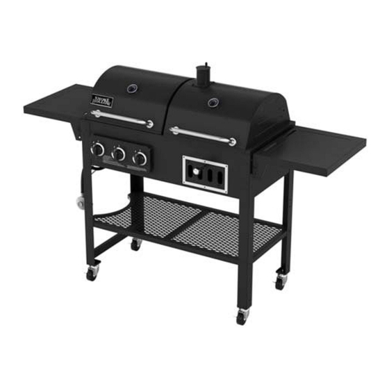
- Page 18 Step 19 Completed Grill Assembly of your grill is now complete. To order a cover for your grill, please visit: www.thesmokercompany.com FOR YOUR SAFETY, FOLLOW ALL SAFEGUARDS AND INSTRUCTIONS...
- Page 19 OPERATING INSTRUCTIONS Connecting the LP gas cylinder to the grill The LP Gas Cylinder must be a 20 pound cylinder and have a Type 1 Cylinder Valve Outlet ● Connector. Handle the Cylinder with care - do not drop it. ●...
-
Page 20: Care And Cleaning
OPERATING INSTRUCTIONS CARE AND CLEANING ! WARNING ! Do not do any cleaning or maintenance on any grill parts until all parts are cool! Be sure ● that the valve on the LP Gas Cylinder is closed and in the OFF position After every cooking session, you may run the gas grill on HIGH, or set the Charcoal ●... - Page 21 OPERATING INSTRUCTIONS ! IMPORTANT ! CURING PROCESS LP GAS GRILL Step 1: Lightly coat ALL INTERIOR surfaces (including interior of lids, cooking grids and area be- low the cooking surface) with vegetable oil or vegetable oil spray. Step 2: Ignite the LP gas grill side and burn at medium temperature for one hour. Step 3: Let the grill cool completely and it is ready for use.
- Page 22 5400 Doniphan Drive Neosho, MO 64850 www.olp-inc.com ©2014 Outdoor Leisure Products, Inc. Smoke Hollow ® and the Smoke Hollow ® logo are trademarks of Outdoor Leisure Products, Inc. and are not to be used without express permission by Outdoor Leisure Products, Inc.
Need help?
Do you have a question about the 3100 and is the answer not in the manual?
Questions and answers