Table of Contents
Advertisement
Quick Links
www.ti.com
EVM User's Guide: LMH6518EVM
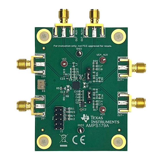
LMH6518 Evaluation Module
Description
The LMH6518 Evaluation Module is designed to aid
in the characterization of Texas Instrument's High
Speed LMH6518 Differential Amplifier. The easy-to-
use evaluation board is designed to provide a quick
setup and offer high performance signal analysis.
The EVM is ready to connect to power supplies, a
signal source, and test instruments through the use of
onboard connectors.
Get Started
1. Order the
LMH6518EVM
Adapter
from ti.com.
2. Visit the
USB2ANY product page
latest version of the USB2ANY Explorer Installer.
3. Connect USB2ANY adapter to PC with the
provided USB cable and connect 10 pin header
to LMH6518EVM.
SNOU200 – OCTOBER 2024
Submit Document Feedback
and
USB2ANY Interface
and install the
Copyright © 2024 Texas Instruments Incorporated
4. Run the USB2ANY GUI and configure the GUI for
SPI communication (instructions for this are in this
user's guide).
5. Type the appropriate byte sequence to configure
the LMH6518 and evaluate device.
Features
•
Designed to work with user friendly USB2ANY
interface adapter and GUI.
•
Board is designed to be easily reconfigurable for
different types of testing conditions.
•
Onboard potentiometer is provided to null any
output offset.
•
Onboard LDO provides the required 3.3V supply
for the VDD pin of the LMH6518, requiring only
one 5V supply.
•
Inputs and outputs include SMA connectors.
•
Designed for connections to standard 50Ω test
equipment.
Description
LMH6518 Evaluation Module
1
Advertisement
Table of Contents

Related Manuals for Texas Instruments LMH6518


Summary of Contents for Texas Instruments LMH6518
- Page 1 USB2ANY Interface • Onboard LDO provides the required 3.3V supply Adapter from ti.com. for the VDD pin of the LMH6518, requiring only 2. Visit the USB2ANY product page and install the one 5V supply. latest version of the USB2ANY Explorer Installer.
-
Page 2: Kit Contents
1.4 Device Information The LMH6518 device is a digitally controlled variable gain amplifier whose total gain is varied from −1.16dB to 38.8dB for a 40dB range in 2dB steps. The −3dB bandwidth is 900MHz at all gains. Gain accuracy at each setting is typically 0.1dB. - Page 3 The USB2ANY is shipped with a USB cable, a 10-pin cable, and a 30-pin cable. For communication with the LMH6518 evaluation board, the 10-pin cable is used as well as the USB cable to interface with the computer.
- Page 4 Hardware www.ti.com Figure 2-3. Selecting SPI Interface 3. Click on the SPI tab and select the settings as shown below that correspond to the LMH6518 SPI functionality. Figure 2-4. SPI Tab Figure 2-5. SPI Configuration LMH6518 Evaluation Module SNOU200 – OCTOBER 2024 Submit Document Feedback Copyright ©...
- Page 5 USB2ANY. Figure 2-7. USB2ANY 10-Pin Header 6. Plug the other end of the ribbon cable into J2 of the LMH6518 evaluation board with the cable key on the side of the key label on the board.
-
Page 6: Basic Operation
LMH6518. For best performance, make sure that the LMH6518 inputs (pins 6 and 7) are both close to VCC/2 (= 2.5V) and there is less than 1mV of difference in voltage between them. On the board, use a DC voltmeter to confirm DC voltage of pins 6 and 7 (top pad of the R7 and right pad of the C23). -
Page 7: Jumper Information
The outputs of the device need to be biased near 1.2V by applying the appropriate voltage to the VOCM (VOCM_Aux) pin for the main (auxiliary) output of the LMH6518. The board has the option of biasing these pins using onboard 1.2V reference circuitry or can be tied to an external bias such as the common mode output control of an ADC. - Page 8 USB2ANY is properly communicating with the LMH6518 is also given in this section. Writing to the LMH6518: To write to the LMH6518, the first bit sent (C7) must be 0. The serial interface protocol write operation is shown Figure 2-11. The data that is read back in the Read data: text field in the USB2ANY GUI needs to be the same as the data written.
- Page 9 Note A way to confirm that writing to the LMH6518 is working properly is to use bit D10 to switch between full power or auxiliary high impedance mode (Aux Hi-Z). When the device is set to Aux Hi-Z mode, the supply current of the device is reduced by about 60mA.
- Page 10 Note When initially writing to the LMH6518, if the data immediately read back is not the same as the data that is written there can be a delay. To fix this, lower the bit rate in the configuration panel found in the SPI tab.
- Page 11 Hardware Filters: The LMH6518 has selectable bandwidth limiting circuitry for both output pairs. The filter options and the corresponding bit values are shown in Table 2-1. Table 2-1. Filter Options FILTER BANDWIDTH (MHz) Full Not allowed Preamp Gain: The preamp function is to control whether the device is in the high gain (38.8dB) setting or the low gain setting (18.8dB).
-
Page 12: Header Information
The header (J2) pinout for the evaluation board is shown in Table 2-4. Table 2-4. Header Information Header Pin Function Chip Select POCI PICO Clock 1,7,9,10 Not Connected LMH6518 Evaluation Module SNOU200 – OCTOBER 2024 Submit Document Feedback Copyright © 2024 Texas Instruments Incorporated... - Page 13 Hardware Design Files 3 Hardware Design Files 3.1 Schematic Figure 3-1. EVM Schematic SNOU200 – OCTOBER 2024 LMH6518 Evaluation Module Submit Document Feedback Copyright © 2024 Texas Instruments Incorporated...
-
Page 14: Pcb Layouts
Hardware Design Files www.ti.com 3.2 PCB Layouts The LMH6518 evaluation board is a four-layer board; all four layers are detailed in Figure 3-2 through Figure 3-5. Figure 3-2. Top Layer Figure 3-3. Ground Layer 2 Figure 3-4. Power Layer 3 Figure 3-5. - Page 15 Vishay-Dale 0402 RES, 100, 1%, 0.1 W, 0603 RC0603FR-07100RL Yageo R17, R20 RES, 0, 0%, 0.2 W, AEC-Q200 Grade 0, 0402 402 CRCW04020000Z0EDHP Vishay-Dale SNOU200 – OCTOBER 2024 LMH6518 Evaluation Module Submit Document Feedback Copyright © 2024 Texas Instruments Incorporated...
- Page 16 Fiducial mark. There is nothing to buy or mount. RES, 0, 5%, 0.1 W, AEC-Q200 Grade 0, 0603 603 ERJ-3GEY0R00V Panasonic RES, 100, 1%, 0.1 W, 0603 RC0603FR-07100RL Yageo LMH6518 Evaluation Module SNOU200 – OCTOBER 2024 Submit Document Feedback Copyright © 2024 Texas Instruments Incorporated...
-
Page 17: Additional Information
Additional Information 4 Additional Information 4.1 Trademarks All trademarks are the property of their respective owners. SNOU200 – OCTOBER 2024 LMH6518 Evaluation Module Submit Document Feedback Copyright © 2024 Texas Instruments Incorporated... - Page 18 STANDARD TERMS FOR EVALUATION MODULES Delivery: TI delivers TI evaluation boards, kits, or modules, including any accompanying demonstration software, components, and/or documentation which may be provided together or separately (collectively, an “EVM” or “EVMs”) to the User (“User”) in accordance with the terms set forth herein.
- Page 19 www.ti.com Regulatory Notices: 3.1 United States 3.1.1 Notice applicable to EVMs not FCC-Approved: FCC NOTICE: This kit is designed to allow product developers to evaluate electronic components, circuitry, or software associated with the kit to determine whether to incorporate such items in a finished product and software developers to write software applications for use with the end product.
- Page 20 www.ti.com Concernant les EVMs avec antennes détachables Conformément à la réglementation d'Industrie Canada, le présent émetteur radio peut fonctionner avec une antenne d'un type et d'un gain maximal (ou inférieur) approuvé pour l'émetteur par Industrie Canada. Dans le but de réduire les risques de brouillage radioélectrique à...
- Page 21 www.ti.com EVM Use Restrictions and Warnings: 4.1 EVMS ARE NOT FOR USE IN FUNCTIONAL SAFETY AND/OR SAFETY CRITICAL EVALUATIONS, INCLUDING BUT NOT LIMITED TO EVALUATIONS OF LIFE SUPPORT APPLICATIONS. 4.2 User must read and apply the user guide and other available documentation provided by TI regarding the EVM prior to handling or using the EVM, including without limitation any warning or restriction notices.
- Page 22 Notwithstanding the foregoing, any judgment may be enforced in any United States or foreign court, and TI may seek injunctive relief in any United States or foreign court. Mailing Address: Texas Instruments, Post Office Box 655303, Dallas, Texas 75265 Copyright © 2023, Texas Instruments Incorporated...
-
Page 23: Important Notice
TI products. TI’s provision of these resources does not expand or otherwise alter TI’s applicable warranties or warranty disclaimers for TI products. TI objects to and rejects any additional or different terms you may have proposed. IMPORTANT NOTICE Mailing Address: Texas Instruments, Post Office Box 655303, Dallas, Texas 75265 Copyright © 2024, Texas Instruments Incorporated...
Need help?
Do you have a question about the LMH6518 and is the answer not in the manual?
Questions and answers