Table of Contents
Advertisement
Quick Links
The LMH1297EVM is an evaluation module designed for high-speed performance and functional
evaluation of the Texas Instruments LMH1297 12G UHD-SDI 75-Ω bidirectional I/O with integrated
reclocker. With this kit, users can quickly evaluate the cable reach and output signal integrity supported by
the LMH1297. High-performance edge-mount BNC connectors are used at the 75-Ω port for the SDI_IO
and SDI_OUT signals, while 100-Ω differential input and output ports are routed to edge-mount SMA
connectors. These connectors facilitate connection to lab equipment or user systems for performance
evaluation. An onboard MSP430 MCU is included to support an optional SMBus or SPI serial control
interface when configuring the LMH1297 operating modes.
......................................................................................................................
1
.......................................................................................................................
2
...................................................................................................................
3
4
..........................................................................................................................
5
5.1
5.2
5.3
6
6.1
6.2
6.3
6.4
7
..................................................................................................................
8
.................................................................................................................
9
1
2
3
4
5
6
7
8
9
10
11
12
13
14
15
16
SNAU205A - March 2017 - Revised August 2019
Submit Documentation Feedback
........................................................................................................
................................................................................................
.................................................................................
................................................................................................
...................................................................................................
...................................................................................................
.................................................................................................
.............................................................................................................
................................................................................................................
.....................................................................................
...............................................................................
.....................................................................................
Copyright © 2017-2019, Texas Instruments Incorporated
SNAU205A - March 2017 - Revised August 2019
LMH1297EVM Evaluation Board
Contents
......................................................................
List of Figures
...............................................
.................................................
.................................................
...................................................
.................................................
...................................................
...............................................
.................................................
..................................................
...................................................
User's Guide
...................
............................
...........................
LMH1297EVM Evaluation Board
2
3
3
3
4
5
7
11
13
13
14
15
18
19
21
23
2
4
5
9
10
11
11
11
11
11
11
12
12
12
12
13
1
Advertisement
Table of Contents

Related Manuals for Texas Instruments LMH1297


Summary of Contents for Texas Instruments LMH1297
-
Page 1: Table Of Contents
With this kit, users can quickly evaluate the cable reach and output signal integrity supported by the LMH1297. High-performance edge-mount BNC connectors are used at the 75-Ω port for the SDI_IO and SDI_OUT signals, while 100-Ω differential input and output ports are routed to edge-mount SMA connectors. -
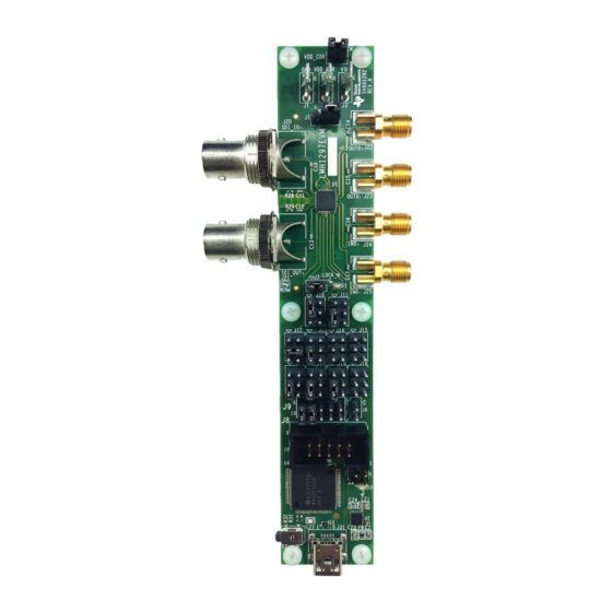
Page 2: Overview
.................. Input and Output Channel Connections Trademarks All trademarks are the property of their respective owners. Overview Figure 1. LMH1297EVM LMH1297EVM Evaluation Board SNAU205A – March 2017 – Revised August 2019 Submit Documentation Feedback Copyright © 2017–2019, Texas Instruments Incorporated... -
Page 3: Features
SMPTE-Compatible Serial Digital Interface • UHDTV/4K/8K/HDTV/SDTV Video • IP Media Gateway • Digital Video Processing and Editing Ordering Information Table 1. LMH1297 Ordering Information EVM ID DEVICE ID DEVICE PACKAGE LMH1297EVM LMH1297RTV QFN (32) SNAU205A – March 2017 – Revised August 2019... -
Page 4: Setup
Figure OUT0+ SDI_IO+ OUT0- IN0+ SDI_OUT+ IN0- Mini-USB Port Connection to PC Figure 2. LMH1297EVM Input and Output Pins LMH1297EVM Evaluation Board SNAU205A – March 2017 – Revised August 2019 Submit Documentation Feedback Copyright © 2017–2019, Texas Instruments Incorporated... -
Page 5: Modes Of Operation
SCL, and GND pins. ADDR0 and ADDR1 pins are used for SMBus address strap. Using either SPI or SMBus mode, users have full access to all register controls in the LMH1297. For convenience, the LMH1297EVM features an on-chip MSP430 that is configured as a USB2ANY interface between LMH1297 and PC through the mini-USB port header on J31. - Page 6 In Pin Mode, EQ/CD_SEL, OUT0_SEL, HOST_EQ0, OUT_CTRL, SDI_VOD, and SDI_OUT_SEL pins control different LMH1297 settings. Using SPI or SMBus, these initial pin control values can be overridden by setting the appropriate override bits through register control. Both SPI and SMBus interfaces allow full control over a wide range of device settings.
-
Page 7: Software/Hardware Description And Setup
By factory default, the LMH1297EVM is configured in CD Mode to accept a valid SDI signal on IN0 and output the retimed data on OUT0, SDI_IO, and SDI_OUT without programming the LMH1297 beforehand. The LMH1297EVM can also be configured by the user to operate in EQ Mode. - Page 8 Either an LMH1218EVM or a second LMH1297EVM in CD Mode can be used as a 100-Ω differential to 75-Ω single-ended converter before the DUT. In this case, either the LMH1218's 75- Ω OUT0+ output or the second LMH1297's 75-Ω SDI_IO+ output can be connected to SDI_IO+ on J20.
-
Page 9: Lmh1297Evm Cd Mode Default Setup For Smbus Operation With Sigcon Architect
Differential Coax Cables LMH1219 OUT0± Control Pin Configuration Notes: J10 (EQ/CD_SEL) = Level H x LMH1297 placed in CD Mode. I/O configured as output. x SDI_IO EQ automatically powered down J11 (OUT0_SEL) = Level L x OUT0 powered up and enabled. -
Page 10: Lmh1297Evm Eq Mode Default Setup For Smbus Operation With Sigcon Architect
Single-ended Coax Cable IN0- Control Pin Configuration Notes: J10 (EQ/CD_SEL) = Level L x LMH1297 placed in EQ Mode. I/O configured as input. x IN0 automatically powered down J11 (OUT0_SEL) = Level L x OUT0 powered up and enabled. x In EQ Mode, OUT0 is always enabled. -
Page 11: Retimed Output At 11.88 Gbps, 5.94 Gbps, 2.97 Gbps, 1.485 Gbps, And 270 Mbps
Figure 8. CD Mode at 5.94 Gbps, Measured at SDI_IO+, Figure 9. EQ Mode at 5.94 Gbps, Measured at OUT0±, Reclocked Output Reclocked Output SNAU205A – March 2017 – Revised August 2019 LMH1297EVM Evaluation Board Submit Documentation Feedback Copyright © 2017–2019, Texas Instruments Incorporated... -
Page 12: Cd Mode At 1.485 Gbps, Measured At Sdi_Io+, Reclocked Output
Figure 14. CD Mode at 270 Mbps, Measured at SDI_IO+, Figure 15. EQ Mode at 270 Mbps, Measured at OUT0±, Reclocked Output Reclocked Output LMH1297EVM Evaluation Board SNAU205A – March 2017 – Revised August 2019 Submit Documentation Feedback Copyright © 2017–2019, Texas Instruments Incorporated... -
Page 13: Sigcon Architect Lmh1297 Gui Profile
SigCon Architect LMH1297 GUI Profile www.ti.com SigCon Architect LMH1297 GUI Profile SigCon Architect GUI can be used to access the LMH1297 register controls easily. There are four pages associated with the LMH1297 profile: • Configuration Page • Low Level Page •... -
Page 14: Low Level Page
SigCon Architect LMH1297 GUI Profile www.ti.com Low Level Page The Low Level Page allows the user to access the LMH1297 registers individually. This page is described in two main sections: • Register Map • Field Description Figure 17 shows the Low Level Page. -
Page 15: High Level Page
Figure 18. LMH1297EVM High Level Page 6.3.1 High Level Interface This interface is dynamic and allows the user to view and control a variety of functions in the LMH1297 concurrently. In this page, the user can easily control functions such as the following: •... - Page 16 Figure 10 shows an example of a macro script that programs two LMH1297 devices, one with SMBus Address 0x5C and another with SMBus Address 0x5A. After this file is saved as a .txt file, the user can run the macro by entering the appropriate file path in the Custom Macro Scripting Utility box.
- Page 17 SigCon Architect LMH1297 GUI Profile www.ti.com Figure 21. Macro Utility Example Log File SNAU205A – March 2017 – Revised August 2019 LMH1297EVM Evaluation Board Submit Documentation Feedback Copyright © 2017–2019, Texas Instruments Incorporated...
-
Page 18: Eye Monitor Page
SigCon Architect LMH1297 GUI Profile www.ti.com Eye Monitor Page The LMH1297 has on-chip eye monitor that can be accessed on the Eye Monitor Page. In this page, the user can control the following: • Perform a single or continuous capture of the eye diagram •... -
Page 19: Bill Of Materials
Power Connector, Receptacle, Mini-USB TE Connectivity 1734035-2 Type B, R/A, Top Mount SMT Header, 100mil, 2x2, Gold, TH Samtec TSW-102-07-G-D SNAU205A – March 2017 – Revised August 2019 LMH1297EVM Evaluation Board Submit Documentation Feedback Copyright © 2017–2019, Texas Instruments Incorporated... - Page 20 Texas Instruments MSP430F5529IPN to 85 degC, 80-pin QFP (PN), Green (RoHS & no Sb/Br) Crystal, 24.000MHz, 20pF, SMD ECS Inc. ECS-240-20-5PX-TR LMH1297EVM Evaluation Board SNAU205A – March 2017 – Revised August 2019 Submit Documentation Feedback Copyright © 2017–2019, Texas Instruments Incorporated...
-
Page 21: Schematics
Green 1.00k 1.00k MODE_SEL MISO_ADDR1 1.00k 20.0k 1.00k 20.0k Copyright © 2016, Texas Instruments Incorporated Figure 23. LMH1297 Schematic Page SNAU205A – March 2017 – Revised August 2019 LMH1297EVM Evaluation Board Submit Documentation Feedback Copyright © 2017–2019, Texas Instruments Incorporated... - Page 22 2.2µF 60 ohm 22µF 0.01µF 1µF 7.5V TPS73533DRBR Copyright © 2016, Texas Instruments Incorporated Figure 24. MSP430 USB2ANY Schematic Page LMH1297EVM Evaluation Board SNAU205A – March 2017 – Revised August 2019 Submit Documentation Feedback Copyright © 2017–2019, Texas Instruments Incorporated...
-
Page 23: Evm Layout
This must be soldered to the copper landing on the PWB. Figure 25. LMH1297EVM Top Layer Figure 26. LMH1297EVM Bottom Layer SNAU205A – March 2017 – Revised August 2019 LMH1297EVM Evaluation Board Submit Documentation Feedback Copyright © 2017–2019, Texas Instruments Incorporated... - Page 24 NOTE: Page numbers for previous revisions may differ from page numbers in the current version. Changes from Original (March 2017) to A Revision ....................... Page ........................• Initial Public Release Revision History SNAU205A – March 2017 – Revised August 2019 Submit Documentation Feedback Copyright © 2017–2019, Texas Instruments Incorporated...
- Page 25 STANDARD TERMS FOR EVALUATION MODULES Delivery: TI delivers TI evaluation boards, kits, or modules, including any accompanying demonstration software, components, and/or documentation which may be provided together or separately (collectively, an “EVM” or “EVMs”) to the User (“User”) in accordance with the terms set forth herein.
- Page 26 www.ti.com Regulatory Notices: 3.1 United States 3.1.1 Notice applicable to EVMs not FCC-Approved: FCC NOTICE: This kit is designed to allow product developers to evaluate electronic components, circuitry, or software associated with the kit to determine whether to incorporate such items in a finished product and software developers to write software applications for use with the end product.
- Page 27 www.ti.com Concernant les EVMs avec antennes détachables Conformément à la réglementation d'Industrie Canada, le présent émetteur radio peut fonctionner avec une antenne d'un type et d'un gain maximal (ou inférieur) approuvé pour l'émetteur par Industrie Canada. Dans le but de réduire les risques de brouillage radioélectrique à...
- Page 28 www.ti.com EVM Use Restrictions and Warnings: 4.1 EVMS ARE NOT FOR USE IN FUNCTIONAL SAFETY AND/OR SAFETY CRITICAL EVALUATIONS, INCLUDING BUT NOT LIMITED TO EVALUATIONS OF LIFE SUPPORT APPLICATIONS. 4.2 User must read and apply the user guide and other available documentation provided by TI regarding the EVM prior to handling or using the EVM, including without limitation any warning or restriction notices.
- Page 29 Notwithstanding the foregoing, any judgment may be enforced in any United States or foreign court, and TI may seek injunctive relief in any United States or foreign court. Mailing Address: Texas Instruments, Post Office Box 655303, Dallas, Texas 75265 Copyright © 2019, Texas Instruments Incorporated...
- Page 30 TI products. TI’s provision of these resources does not expand or otherwise alter TI’s applicable warranties or warranty disclaimers for TI products. Mailing Address: Texas Instruments, Post Office Box 655303, Dallas, Texas 75265 Copyright © 2019, Texas Instruments Incorporated...
Need help?
Do you have a question about the LMH1297 and is the answer not in the manual?
Questions and answers