Table of Contents
Advertisement
Quick Links
Operating, Installation
and Maintenance
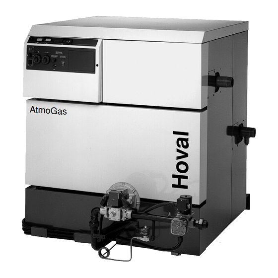
Manual for AtmoGas
AG140 - AG340 boilers.
AG 006 / October 2000
Contents
Introduction . . . . . . . . . . . . . . . . . . . . . . . . . . . . . . . . . . . . . . . . . . . . . . . . . 2
. . . . . . . . . . . . . . . . . . . . . . . . . . . . . . . . . . . . . . . . . . . 3
1.1
Technical specifications . . . . . . . . . . . . . . . . . . . . . . . . . . . . . 3-4
1.2
Main dimensions . . . . . . . . . . . . . . . . . . . . . . . . . . . . . . . . . . . . . . . . . 5
3.1
Boiler location . . . . . . . . . . . . . . . . . . . . . . . . . . . . . . . . . . . . . . . . . . 7-8
3.2
Gas connections . . . . . . . . . . . . . . . . . . . . . . . . 9
3.3
Flues and chimneys . . . . . . . . . . . . . . . . . . . 9-10
3.4
Hydraulic connections . . . . . . . . . . . . . . . . . . . 11
3.5
Filling the system . . . . . . . . . . . . . . . . . . . . . . . 11
6.1
6.2
Starting up . . . . . . . . . . . . . . . . . . . . . . . . . 14-15
9.1
Cleaning the burner . . . . . . . . . . . . . . . . . . . . . 19
9.2
Cleaning the heating sections . . . . . . . . . . . . . 20
9.3
Painted surfaces. . . . . . . . . . . . . . . . . . . . . . . . . 20
9.4
Identification plate . . . . . . . . . . . . . . . . . . . . . . . 20
. . . . . . . . . . . . . . . . . . . . . . . . . . . . . . . 5-6
. . . . . . . . . . . . . . . . . . . . . . . . . . . . . . . . . . . . . . 7
. . . . . . . . . . . . . . . . . . . . 13
. . . . . . . . . . . . . . . . . . . . . . . 14
. . . . . . . . . . . . . . . . . . . . . . . . . . . . . . . . 15-16
. 16-18
. . . . . . . . . . . . . . . . . . . . . . . . . . . . 19
. 21-30
10/00 - 94858086 - 8350-4369 B
. . . . 12
Advertisement
Table of Contents

Related Manuals for Hoval AtmoGas AG140


Summary of Contents for Hoval AtmoGas AG140
-
Page 1: Table Of Contents
Operating, Installation and Maintenance Manual for AtmoGas AG140 - AG340 boilers. AG 006 / October 2000 Contents Introduction ..........2 1. -
Page 2: Introduction
Introduction AG 006 / October 2000 Introduction These instructions have been written to give a brief description of the Hoval AtmoGas AG boilers, their For completion installation, commissioning, operation and subsequent by Boiler Attendant maintenance. The installation of boilers and their ancillary equipment... -
Page 3: General
1. General AG 006 / October 2000 1. General AtmoGas AG boilers are cast-iron boilers with a two stages atmospheric gas burner and electronic ignition via an ignition burner. They are designed for use with a hot-water central heating system, and have an output rating of 140 - 340 kW. - Page 4 1. General AG 006 / October 2000 Type of boiler AG 140 AG 160 AG 180 AG 200 AG 220 AG 260 AG 300 AG 340 119 to 136 to 153 to 170 to 187 to 221 to 255 to 289 to 2nd stage 140 (1)
-
Page 5: Main Dimensions
1. General AG 006 / October 2000 1.2 Main dimensions 8350N001 B øJ Threaded water flow tapping AG 140 1044 1210 2” 1” Threaded water return tapping AG 160 1132 1210 2” 1” Tapped gas inlet AG 180 1220 1210 2”... -
Page 6: Description
2. Description AG 006 / October 2000 Operation of boilers fitted with a LGD 12.01 safety box. - Normal operating cycle Operating principle : The boiler can operate in the 2nd or 1st stage, TCH1 depending upon the needs of the installation in terms of heat. -
Page 7: Installing And Connecting The Boiler
3. Installing and connecting the boiler AG 006 / October 2000 3. Installing and connecting the boiler 3.1 Boiler location G The figures indicate the minimum recommended dimensions for providing easy access around the boiler. G Leave clearance equal to dimensions a and b for assembly tools (simplified JD tools for boilers with 8 - 14 sections, or JD-TE tools for boilers with 8 - 18 sections) :... -
Page 8: Boilerhouse Ventilation
3. Installing and connecting the boiler AG 006 / October 2000 natural or mechanical extraction. Mechanical extract Boilerhouse Ventilation ventilation with natural inlet must not be used. Detailed recommendations for air supply are given in BS6644. Where a mechanical inlet and mechanical extract system is applied the design extraction rate should The permanent ventilation of the boilerhouse (not not exceed one third of the design inlet rate. -
Page 9: Gas Connections
Hoval AtmoGas AG boilers together with their associated systems. Hoval advise contact directly with major specialists on water treatment such as Grace Dearborn or Houseman. - Page 10 (1993) are maximum 260 mg/kWh (148 brick stack or double skin steel chimney. This helps p.p.m at 0% 0 ). Burners supplied with Hoval boi- prevent condensation. lers fully meet this requirement. •...
-
Page 11: Hydraulic Connections
The complete filling and draining down of the heating circuit must be carried out by the Heating Engineer prior to commissioning. Hoval will commis- sion if requested. Water Flow & Return Temperatures Consideration will already have been given to the sys- tem flow and return temperatures but please note : 1. -
Page 12: Setting The Pressure At The Injection Nozzles To Adapt The Boiler Power
AG 006 / 4. Setting the pressure at the injection nozzles to adapt the boiler power October 2000 4. Setting the pressure at the injection nozzles to adapt the boiler power G Do not start up the boiler without making sure that the points given under paragraph 6.1 have been checked. -
Page 13: Setting Pressures And Calibrated Injection Nozzle Markings
AG 006 / 5. Setting pressures and calibrated injection nozzle marketings October 2000 Setting pressures and calibrated injection nozzle markings Pressure/flow rate and injection nozzle marking table - 15°C - 1013 mbar Type of boiler AG 140 AG 160 AG 180 AG 200 AG 220 AG 260 AG 300 AG 340 119 to 136 to 153 to... -
Page 14: Commissioning
TopTronic controller. G Hand operation : it must be selected when When a Hoval Engineer is engaged to commis- the boiler is not fitted with a TopTronic controller. sion the boiler the following items are checked... -
Page 15: Fitting A Toptronic Controller
6. Commissioning AG 006 / October 2000 7. Boiler thermometer. 7. Fitting a TopTronic controller The control panel may be fitted with an optional 8. 3.15 Amp. Fuse. It is accessible from the boiler TopTronic controller. control panel, and is designed to protect the burner The optional units are easily assembled in the housing control circuit. -
Page 16: Electrical Connections
7. Fitting a TopTronic controller AG 006 / October 2000 4- Fitting the TopTronic controller : 8. Electrical connections Plug in the four connectors to the rear of the TopTronic Important : Electrical connections should be Controller. carried out by a qualified professional only. Connecting to the mains The connection to the mains must comply with applicable standards and regulations. - Page 17 8. Electrical connections AG 006 / October 2000 G Connection under the control panel G Connecting to the strips Check if the following connectors are in place under Make the electrical connections to the two marked the control panel. horizontal strips located inside the control panel. - Pull the connecting cables into the boiler through the cable gland designed for this purpose on the top rear panels, and place them in the cable ways located...
- Page 18 8. Electrical connections AG 006 / October 2000 Standard electrical diagram for AG 140-340 boilers 8350N157 (8350-4381 C) Note : For other (job-specific) wiring configurations, a separate wiring diagram will be issued with the boilers.
-
Page 19: Maintenance
9. Maintenance AG 006 / October 2000 9. Maintenance Clean the burner regularly for unit efficiency. Cleaning is recommended once a year. 9.1 Cleaning the burner 8350N125 B Removing the burner : Cleaning the main burner and the ignition burner : - Brush the burner rails with a soft brush or using a - Cut off the power supply to the boiler. -
Page 20: Cleaning The Heating Sections
9.1 : Manufacturing date • Remove the cover. • Remove the top insulating material. • Open the sweeping trap of the flue gas removal unit. Hoval LTD, Northgate, Newark Hoval Notts, NG 24 1JN Tel: 01636 672711 Type Year •... -
Page 21: Exploded View Diagrams And List Of Spare Parts
10. Exploded view and list of spare parts AG 006 / October 2000 10 Exploded view and list of spare parts Note : While ordering spares, do not forget to state the code number given opposite the description of the required part in the list. - Boiler body 8350N107... - Page 22 10. Exploded view and list of spare parts AG 006 / October 2000 - Body insulation 8350N113 8350N154...
- Page 23 10. Exploded view and list of spare parts AG 006 / October 2000 - 20 mbar GAS LINE (before 10/2000) 8350N152...
- Page 24 10. Exploded view and list of spare parts AG 006 / October 2000 - 20 mbar GAS LINE (after 10/2000) 8350N159...
- Page 25 10. Exploded view and list of spare parts AG 006 / October 2000 - Control panel 8350N153...
- Page 26 10. Exploded view and list of spare parts AG 006 / October 2000 Ref. Code no. DESCRIPTION Ref. Code no. DESCRIPTION Boiler body 8345-7110 Assembled combustion chamber, AG 260 8345-7016 8345-7112 Assembled combustion chamber, AG 300 Complete left-hand side section 8345-7015 8345-7114 Assembled combustion chamber, AG 340...
- Page 27 10. Exploded view and list of spare parts AG 006 / October 2000 Ref. Code no. DESCRIPTION Ref. Code no. DESCRIPTION 9425-0277 Tray insulation, 612 wide, AG 220 & 300 Boiler body insulating material 9425-0278 Tray insulation, 700 wide, AG 140 & 300 8345-8745 Boiler body insulation, AG 140 9425-0279...
- Page 28 Lock nut 8350-8686 Upper front panel, AG 140 8345-7057 Bag of screws for casing 8350-8687 Upper front panel, AG 160 9486-1632 Logo HOVAL 8350-8688 Upper front panel, AG 180 9486-1633 Logo AtmoGas 8350-8689 Upper front panel, AG 200 8350-8690 Upper front panel, AG 220...
- Page 29 10. Exploded view and list of spare parts AG 006 / October 2000 Ref. Code no. DESCRIPTION Ref. Code no. DESCRIPTION Gas line 8350-8528 HONEYWELL gas line (AG 140-180) 9501-3066 Flat seal, 62 x 46 x 2 (AG 200-220) 8350-8529 HONEYWELL gas line (AG 200-220) 9501-3067 Flat seal, 78 x 60 x 2 (AG 260-340)
- Page 30 10. Exploded view and list of spare parts AG 006 / October 2000 Ref. Code no. DESCRIPTION Ref. Code no. DESCRIPTION Control panel 8350-8634 Complete control panel 8350-8802 Front panel + rear box 8250-0566 Cover 8116-8288 Fastening flange 9521-6280 Yellow indicator light 9536-5157 Flat thermometer 9532-5091...
- Page 31 Notes AG 006 / October 2000...
- Page 32 Conservation of Energy Protection of the Environment HOVAL Limited, Northgate, Newark, Notts NG24 1JN Tel : 01636 672711 Fax : 01636 673532...
- Page 33 Assembly Atmogas AG 140-340 AG 006 / October 2000 Assembly Atmogas 140-340 Tools required : Packaging : - 8 spanner The tables below provide the number of packages which - 10 spanner make up the boiler. The packages are listed in the order - 13 spanner in which they are opened during assembly.
- Page 34 Assembly Atmogas AG 140-340 AG 006 / October 2000 G Boiler with assembled body Type of boiler - Gas line package, 20/25 mbar, DP169 DP170 DP171 DP172 DP173 DP174 DP175 DP176 with underframe - Assembled boiler AV111 AV112 AV113 AV114 AV115 AV117 AV119...
- Page 35 Assembly Atmogas AG 140-340 AG 006 / October 2000 Assembling the heating sections 8350N052 Proceed as follows before mounting the sections on the 8350N086 underframe : - Fix the two lower casing brackets A, using - remove tray A located under the burner drawer. three H5 nuts + DE5 washers.
- Page 36 Assembly Atmogas AG 140-340 AG 006 / October 2000 8350N089 8350N090 Clean the fittings with thinner. Coat them with the Fit the first intermediate element. lubricant supplied with the sections. Put the assembly tool in place. Press in the two nipples moderately, using a piece of Tighten gradually so as to bring about simultaneous and wood.
- Page 37 Assembly Atmogas AG 140-340 AG 006 / October 2000 8350N093 - Put the combustion chamber in as shown above and fasten it to the underframe at the front and rear with the 8350N094 six H 8x30 screws E and six DE8 serrated washers Fit the burner drawer into the grooves designed for this (with a 13 spanner) which were removed in step 1.
- Page 38 Assembly Atmogas AG 140-340 AG 006 / October 2000 Assembling the insulation 8350N069 8350N099 8350N100 - Place front insulation panel A. Insert it into metal Fix panel-support cross-piece G onto fastening retaining bracket E located at the bottom of the points F with two H 8x30 screws, two H8 nuts, two combustion chamber DE8 serrated washers (13 spanner) and four flat...
-
Page 39: Assembling The Casing
Assembly Atmogas AG 140-340 AG 006 / October 2000 8350N104 - Insert rear insulation panel D between the body of - Place upper insulation panel E on the draught the boiler and the draught diverter (see detailed diverter drawing). Insert the bottom of the panel into the two - Turn the two casing fastening brackets F outwards, retaining brackets K designed for this purpose. - Page 40 Assembly Atmogas AG 140-340 AG 006 / October 2000 8350N106 8350N071 - Fix the left and right-hand rear panels onto sockets A Fit the two horizontal wiring ducts along the left and on the front side panels, clip them into rivet studs B right-hand side panels.
- Page 41 Assembly Atmogas AG 140-340 AG 006 / October 2000 Gas line assembly 8350N074 A - If necessary, loosen the two pilot flame fastening screws B slightly, and position the pilot flame behind the cut-out of the combustion chamber plate and fasten the screws. - Connect the gas supply line to pilot flame C.
- Page 42 Assembly Atmogas AG 140-340 AG 006 / October 2000 Inserting cables into left-hand Inserting the cables into flange with pocket the left-hand flow flange 8350N096 8350N097 8345N018 8350N073 A - The cables must necessarily be placed in the pocket Fit the cable form into brackets A, thread them through located on the left-hand side of the boiler.
- Page 43 Assembly Atmogas AG 140-340 AG 006 / October 2000 8350N121 8350N120 - Fix lower rear panel E with SIM screws and fasten Clear right-hand rear plate B (not fixed) and put the the screws. top in place. - Clip on covers F with the rivet studs. - Adjust the position of the casing by tightening or loosening the two fastening nuts on casing brackets 8350N122...
- Page 44 Conservation of Energy Protection of the Environment HOVAL Limited, Northgate, Newark, Notts NG24 1JN Tel : 01636 672711 Fax : 01636 673532...
Need help?
Do you have a question about the AtmoGas AG140 and is the answer not in the manual?
Questions and answers