Table of Contents
Advertisement
Quick Links
Advertisement
Table of Contents

Related Manuals for HELI gleen CPD15SH-GB2


Summary of Contents for HELI gleen CPD15SH-GB2
- Page 2 OPERATION & SERVICE MANUAL Three-wheel battery forklift truck with rear drive axle...
- Page 3 FORWARD Three-wheel battery forklift trucks with rear drive axle are the new offering of HELI to meet the needs of market. They are environment friendly products. They are applied to handle and stack goods in stations, ports, logistics transportation enterprises,...
-
Page 4: Table Of Contents
CONTENTS FOREWORD 1. Safety Instructions of Operation and Driving………………………………………1 2. External view of the Forklift Truck…………………………………………………5 3. Specification………………………………………………………………...………6 4. Drive Equipment……………………………………………………………………8 5. Front Axle………………………………………………………………….………13 6. Brake System………………………………………………………………………18 7. Steering System……………………………………………………...…………….26 8. Electric System ……………………………………………………………………31 9. Hydraulic System………………………………………………………….………63 10. Lifting System……………………………………………………………………67... -
Page 5: Safety Instructions Of Operation And Driving
1. Safety Instructions of Operation and Driving 1.1 Drivers and equipment keepers should keep “safety first” in mind and operate according to the operation and service manual. 1.2 Transporting Pay attention to the following instructions before transporting the forklift with containers or trucks. - Page 6 Fig. 1-1 Arrangement of the operation levers 1.liquid crystal display 2.lighting and turn signal switch 3.key switch 4.steering hand-wheel and horn 5. forward and backward switch 6.parking brake lever 7.brake pedal 8.accelerator pedal 9.the forth operation lever 10.the third operation lever 11.tilting operation lever 12.lifting operation lever 13.emergncy switch 1.4.2 Check all instruments for normal functions.
- Page 7 1.5 Precaution during driving 1.5.1 Grasp the handle on the left side of the forklift when getting on the forklift. Do not grasp the hand wheel. 1.5.2 Pay attention to the state of mechanical, hydraulic, electrical system and MOSFET speed adjuster. 1.5.3 Pull the plug into the battery plug, pull up the emergency switch, turn on the key switch, set the direction to the desired position, depress the accelerator pedal gradually and keep suitable acceleration speed.
- Page 8 company. 1.5.15 Check the chain regularly. 1.5.16 According to the measurement method specified in JB/T3300, the maximize noise at the outboard of the forklift should be no more than 80dB(A). 1.6 Charging 1.6.1 Obey the stipulations strictly in operation instruction for battery when first charging or recharging.
-
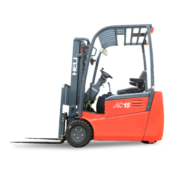
Page 9: External View Of The Forklift Truck
2. External view of the Forklift Truck... -
Page 10: Specification
3. Specification Model CPD15SH-GA1/ CPD15SH-GB1/2/3 CPD13SH-GB1/2/3 Load Capacity 1500 1500 1250 Load Center Standard Mast Lift Height 3000 3000 3000 Mast Tilt Angle(Front/Rear) Height with fork to the ground (Mast 1975 1975 1975 Vertical) Free Lift Height Height with Mast Extended ( with 4008 4008 4008... - Page 11 Size and weight of main assemblies Model CPD15SH-GA1/ CPD13SH-GB1/2/ Unit Specification Size 450× 974× 873 396× 974× 873 Counterbalance Weight Size 1278× 974× 1579 1278× 974× 1579 Overhead Guard Weight 60.6 60.6 Size 295× 940× 1885 295× 940× 1885 Mast(Lifting Height 3000mm)...
-
Page 12: Drive Equipment
4. Drive equipment 4.1 Drive equipment (standard type, for GA model) 4.1.1 Drive equipment brief description The drive equipment mainly is mechanical reducer box. Refer to the table 4-1 for its main specifications and figure 4-1 for drive equipment assembly. The working principle is that: the output shaft of the motor is connected with the small gear (part 10) through spline. - Page 13 1.case base 2.roller bearing 3.shim 4.spacer 5.shim 6.roller bearing 7. shaft 8.locking nut 9. large gear 10. small gear 11.screw 12.washer 13.bolt 14.washer 15.bearing support 16.bolt 17.washer 18.roller 19.bolt 20.O-ring 21.shim 22.pin 23.oil seal 24.snap ring 25.screw 26.washer 27.screw 28.bolt 29.
- Page 14 block; 2) Turn the steering hand wheel and male the fixing side of the drive wheel nut (part 29)face outside; 3) Remove all nuts(part 29 in fig4-1)from the wheel 4) Take out the drive wheel 4.1.3 Drive wheel installation 1) Fix the drive wheel and make the hole of the wheel fits bolt (part 28 in fig4-1)of the drive wheel.
- Page 15 Item Item Type Stepless speed Ratio(forward gear ) 25.23 Ratio(reverse gear ) 25.23 φ457×157 Drive wheel(diameter× width) Type of oil 80W/90GL-5 Gross weight(no include motor and drive 103Kg wheel) Figure 4-2 Mechanical transmission box structure 1. reducer case cover 2. transmission box plate 3.
- Page 16 34. small gear 35. nut 37. hub bolt 38. rim nut 39. oil seal holder 40.oil seal 41. O ring 42. bearing 43. retainer ring 44. retainer ring 45. spacer bush 46. drive axle 47. spiral bevel gear 48. spacer bush 49.
-
Page 17: Front Axle
5. Front Axle 5.1.The main specifications of the front axle see table 5.1 Rated capacity 1-1.5T Type Wet type front axle Cast-installing type Planetary gear type reduction ratio Friction discs number Spacer number Oil amount 300-350ml 5.2.General description The front axle consists of output half-shaft(part31), planet carrier(part 25) planetary gear assembly(part23),inner gear(part24),sun gear(part22), friction disc (part10)... - Page 18 are limited about the outside by the circumferential ring gear(part24).and the opposite direction is limited by the snap ring(part7) to the shell cover(part20).the discs clutch-inner(part9) are connected with the sun gear(part22) by the rear involute gear as one unit. The brake cylinder assembly (part16) is located to the shell cover (part19) by the pin (part17).One end of the cylinder assembly (part16) is connected to the bar (part14), and the other end is to the shell cover (part19).
- Page 19 the service brake is released. Brake cable is connected to the brake cylinder assembly (part16) through the screw hole. the brake cylinder assembly(16) revolves around the pin(part17) when pulled the brake cable. Then the head of the assembly pushes the bar (part14) moves ahead and push the sliding bearing (part13) to enable the friction discs and the spacers to be locked together.
- Page 20 Fig 5-2 parts of axle ass’y sectional view Fig 5-3 brake cylinder ass’y sectional view AP613-02011 housing(right) AP613-02041 Sun gear housing A75B3-42221 washer A75B3-42231 spring A75B3-42361 Oil seal55X80X10 A75B3-42081 Sun gear Z-32011 Bearing32011 A75B3-40231 Planetary assy B8030-10030 screwM10x30 A75B3-42181 Ring gear B0230-08035 boltM8x35 A75B3-42191 Planet carrier...
- Page 21 5.3 Trouble shooting Fault Causes Remedy Improper gear clearance in the first stage speed Regulate Loud noise reducing Worn or broken bearing in Replace the shell cover Oil leaks from the flange Loose lock nut of the Regulate of the haft shaft Worn of the friction discs Replace Poor wet-type brake...
-
Page 22: Brake System
6. Brake System 6.1 General Description The brake system consists of brake pedal mechanism, master cylinder, pipe system and oil-cooled wet-disc brake. The wet-disc brakes are installed in the front axle and the friction linings are cooled by the oil. This eliminates the damage caused by dust and foreign bodies, avoids overheating, reduces the wear of friction lining,... - Page 23 Adjustment of brake pedal 1) Make the push rod short 2) Adjust the pedal to the height shown in Fig. 6-1 with stopper bolt, tighten the locking nut 3) Adjust the push rod until the clearance between the push rod and master cylinder piston to 0-1mm Tighten the push rod locking nut 6.1.2 Master cylinder...
- Page 24 Fig. 6-2 Master Cylinder 1. Link rod 2. Push rod 3. Dust cover 4. Snap ring 5. Secondary cup 6. Piston 7. Primary cup 8. Spring 9. Check valve As the brake pedal is released, the piston is forced back by the return spring. At the same time, the brake fluid in each operating cylinder is pressurized by the return spring, returning into the master cylinder through the check valve.
- Page 25 Fig.6-3 Connecting between the brake and front axle a) Connecting of the service brake The brake pipe joint (item 3) connects to the top right threaded hole and the brake pipe (item 4), tightening torque: 12-16 Nm. When placing the brake pipe, the bending radius should be kept as large as possible to keep the resistance against the restoring forces for lifting the break as small as possible.
- Page 26 pedal. b) Loosen the bleeder valve (item 2), bleed the brake system. c) When brake fluid escapes without bubbles, press the brake pedal, tighten the bleeder valve, tightening torque: 50Nm. d) Check the braking effect 6.1.5 Parking Brake Lever The parking brake lever is of teeth type as shown in figure 6-4. One end of the brake cable is connected to the driven arm of the parking brake lever through pin and the other end is fixed to the brake sub cylinder through the cable connector.
- Page 27 Fig. 6-4 parking btake 1.Sector gear plate 2.lock 3.rod 4.handle sets 5.pad 6.spring 7.nut 8.button 9.cable (each side has one) 6.1.6 Brake system operation There are two independent braking systems: service brake and parking brake. Press the brake pedal and the service brake works; the parking brake knob is on the left side of the instrument panel.
- Page 28 6.2.1 Checking and Maintenance of the Brake System a) Parking brake (daily check) First check if the parking brake functions well; then check if the inching switch works when parking brake is pulled up, that is the electricity power can be disconnected.
- Page 29 b) Adjust the pedal to height with the stopper bolt. c) With the brake pedal depressed by the idle stroke, pull the rod out until its front end is 1mm distant from the master cylinder piston. d) Tighten the push rod locking nut. 6.2.3 Adjustment of brake switch a) Loose the brake switch locknut, after adjusting the pedal height b) Pull the plug, separate the wire...
-
Page 30: Steering System
7 Steering System 7.1 General Description The steering system consists of steering hand-wheel, steering column, steering shaft, powered steering unit with load sensing, priority valve and steering motor assembly. The steering controls are installed on the instrument panel assembly (Fig. 7-1). - Page 31 priority valve, steering unit and steering motor are used for steering. When do not turn the steering hand-wheel, the priority valve is at the equilibrium, only a little oil flow back to the tank, Most of oil flow to other circuit. When turning steering hand-wheel, the variable throttle valve port is opened and the oil pressure in steering system is changed.
- Page 32 gearⅠmeshes with the he steering gearⅡ, the hydraulic motor steers the truck. 7.2 Adjustment and Maintenance 7.2.1Installation of steering wheel a) Make sure the mounting surface of wheel shaft and wheel is clean, check the shaft and wheel whether have damage; b) Assure alignment of rim holes and hub bolts;...
- Page 33 several times to exhaust air from the hydraulic pipeline and the steering cylinder; b) Turn the steering hand-wheel right and left, check the steering power whether is smooth; c) Turn the steering hand-wheel right and left, check the connection of the hydraulic pipeline whether is correct.
- Page 34 Exhaust air: start pump motor and slowly turn the steering hand-wheel right and left several times, exhaust the air in steering system. If there are any abnormal situations in this process, we should turn off the power, find out the cause and troubleshoot...
-
Page 35: Electric System
8 Electric System Dual electric controlling system with high performance is applied in this truck. It can provide quite, efficient, smooth and safe control for the vehicle. The electric system is formed with the control system, the display, motors, batteries, switches, lights and wiring harnesses. 8.1 Control system 8.1.1 DANAHER Control system (for CPD15SH-GA3) DANAHER control system for this truck is combining with a traction controller,... - Page 36 Traction Controller: ACS24S-23P 24V 500A Pump Controller: ACS24XS-35P 24V 350A The Kollmorgen manufactured AC super controller (ACS) is the key component for the driving and speed control of a forklift. Benefit by its state of the art AC technology with flux vector control, ACS greatly increases the performance and the operate efficiency of the vehicle, and also with it’s high torque-to-inertia ratio, outstanding reliability, wide range of motor speed control, good torque and speed characteristic, regenerate braking function, CAN open interface and digital control of...
- Page 37 Fig.8-2 The circuit diagram of electric system...
- Page 38 8.1.2 ZAPI control system (for CPD15SH-GA2,CPD15SH-GB2,CPD13SH-CB2) ZAPI control system includes traction controller, pump controller, contactor etc. The controller is the core component of the system, which can provides excellent control to vehicle AC traction motor. When the truck has a default, but also can stop it quickly, to protect the driver and motor effectively.
- Page 39 1) Battery polarity protection 2) Connections errors protection 3) Thermal protection; overloaded protection; short circuit protection 4) Controller protection degree IP54 5) Out of control protection 6) Over discharging protection 7) Operation order protection c) Console functions: 1)Adjustment of parameters and changes to the inverter’s configuration on-line; 2)Adjustment of accelerator signal on-line;...
- Page 40 Number associated in CAN BUS net Module SICOS TRACTION TRACTION MASTER TRACTION SLAVE PUMP EPS-AC MHYRIO/HVC SMART DISPLAY Table 8-1 CAN BUS MODULE Notice Any variations or special requirements should be made after consulting a ZAPI agent. The supplier is not responsible for any problem, if you mended without authorizatio...
- Page 41 Fig.8-4 The circuit diagram of electric system...
- Page 42 8.1.3 CURTIS control system (CPD15SH-GA1) CURTIS control system includes traction controller, pump controller, contactor etc.The controller is the core component of the system, which can provides excellent control to vehicle AC traction motor. When the truck has a default, but also can stop it quickly, to protect the driver and motor effectively.
- Page 43 2) Connections errors protection 3) Thermal protection; overloaded protection; short circuit protection 4) Controller protection degree IP65 5) Out of control protection 6) Over discharging protection 7) Operation order protection c) Console functions: 1)Adjustment of parameters and changes to the inverter’s configuration on-line; 2)Adjustment of accelerator signal on-line;...
- Page 44 Figure 8-6 CURTIS system electric principle diagram...
- Page 45 8.2 Combined Instrument 8.2.1 OPT10 meter The meter that is used in a DANAHER system is the OPT10. The OPT10 is a multifunctional, microprocessor based operator terminal that can be factory or user defined to monitor various functions, input of user action and more. Fig.8-7 OPT10 meter a) Features: •...
- Page 46 • The OPT10-unit is a slave unit that needs to be connected to a CAN open master. • Four-level functionality for normal user or service use. • 2x255 definable error/warning/information strings. • Standard CAN open interface for simple and reliable communication. •...
- Page 47 will display the error code and the error information, as shown below, the error code would be 104 and “tract pot value out of range error” indicates the pedal is either not well connected or damaged. Figure 8-8 OPT10 meter Notice: Please refer to table 8-2 for error code explanations.
- Page 48 AT KEY ON PSPEED2 SWITCH ACTIVE The pump speed2 switch is on when key on AT KEY ON PSPEED3 SWITCH ACTIVE The pump speed3 switch is on when key on AT KEY ON PSPEED4 SWITCH ACTIVE The pump speed4 switch is on when key on AT KEY ON PUMP POT VALUE OUT OF The value of pump pot is out of range(<30 or >2800)
- Page 49 MOTOR TEMP HIGH Motor temperature is higher than 145° C MOTOR TEMP SENSOR Motor temperature sensor not connected or short circuit SPEED SENSOR Speed sensor not connected or short circuit HIGH VOLTAGE The ACS voltage is higher than 98V LOW VOLTAGE The ACS voltage is lower than 60V DEFAULT PAR.
- Page 50 vehicle state. means turtle speed. When the controller is default or the low battery charge, will flash .When batery charge is lower than the value set, will light and flash. c) Fault reading d) The red LED will flash, the will light on and the fault code will display when there is alarm.
- Page 51 MOTOR TEMPERAT High motor temperature BATTERY LOW Battery low BATTERY LEVEL #2 Battery level #2 BATTERY LEVEL #1 Battery level #1 CURRENT SENS. KO Current sensing fault POWER FAILURE#3 Power failure #3 HIGH CURRENT high current POWER FAILURE #2 Power failure #2 POWER FAILURE #1 Power failure #1 DRIVER SHORTED...
- Page 52 MOTOR STALL Pump motor temperature sensor fault MASTER KO Tractor master fault NO CAN MAS N. 3 No CAN message in node 3 THERMIC SENS. KO Temperature sensor fault INPUT MISMATCH Poor input contact WAITING FOR N.3 Wait for node 3 signal AUX OUTPUT KO Auxiliary output fault ENCODER LOCKED...
- Page 53 temperature sensor or harness has fault”. if “pump 47” occurs, it means “incorrect pump operation order” is detected. Figure 8-11 Curtis 840 meter fault display Fault Fault code shown in the hand Possible reasons code console shown in meter Controller Overcurrent 1.Motor external connecting end U, V or W has short circuit.
- Page 54 3.Check if there is anything else consume battery. 4.high battery internal resistance 5.battery unconnected when driving 6. refer to 1311battery monitor menu: capacitor voltage 7. B+fuse is burn or main contactor unconnected Overvoltage Cutback 1. Normal operation, the fault shows the regenerated brake 2,4 current increases battery voltage when regenerated brake acts.
- Page 55 Motor Open 3,7 1.motor U、V、W phase has open circuit. 2.cable is damaged or improperly connected. Main Contactor Welded 1.main contactor pin end connects. 3,8 2.Motor U phase is unconnected or open circuit. 3.A alternant voltage way (such as a external precharging resister ) supplies a current a current to capacitor group (B+ terminal).
- Page 56 2. Motor encoder fault. 3.Harnness damaged or improper connected. 4.Encoder power supply has fault. 5.Refer to 1311 motor monitor menu: motor RPM. Motor Characterization Fault 1.Motor character description fault. 8,7 Encoder Characterization 1.Encoder character description fault. 8,8 Fault 2.motor encoder pulse frequency is not a standard value(32, 48,64,80ppr)...
- Page 57 housing of the motor has cracks; check if the foot screw and the end cap screw of the motor are loose. (2) Check the ventilation and environment of the motor; keep the motor clean; the ambient environment should be less than 40℃. (3) Check if the working current exceeds the rated current.
- Page 58 2. fuse is burnt; 2. find out the fuse burning 3. Incorrect connecting reasons and then change a new of the controller circuit; one; 4. cur circuit of the stator 3. check if the circuit is properly or rotor winding; connected correct 5.
- Page 59 Great vibration 1. improper installment 1. reassemble; when of the gears; 2. check the bearing clearance or motor 2. bearing is worn out, change the bearing; working. the clearance is big; 3. clean the rotor and tighten the imbalance screw; rotator;...
- Page 60 8.3.4 Operating ambient Motor can be operating as follows: below sea level 1200mm ambient temperature from-25℃~+40℃ opposite humidity to100% Notice: In case of danger, one must shut off the power when examining and maintaining the motor. 8.4 Battery 8.4.1 Construction Traction batteries are made of negative plate, positive plate, cell, cover and electrolyte.
- Page 61 say. a) Battery maintenance and notes 1) Keep the surface of the battery clean and dry. Maintain the pole pillar, bolts and connecting parts often. If it is loose or poor connected, remove it; 2) Never put any object that can conduct electricity on the battery avoiding battery short circuit;...
- Page 62 9) During the usage of the battery, carry out one equalizing charge once a month to keep the good equalizing condition of each unit during the usage; b) Battery storage 1) The batteries should be stored in a storehouse, which is dry, clean and well ventilated ,and the temperature stays between 5-40°...
- Page 63 electrolyte is dilute sulfuric acid. So please wear safe guard when testing battery, adding liquid, regulating and carrying out other operations in preventing of accident. ○ The housing of the charger is metallic conductor. Make sure the wiring of the motor to earth is well connected in preventing of electric shock accident. ○...
- Page 64 time. 8.Discharge over current undercurrent 9.The electrolyte isn’t pure. Partial short circuit inside electricity leakage Short circuit 1.The voltage of 1.Replace plate 1.The plate curve、 inside battery is very 2.Offload the precipitate and Reactive matter low during conducting matter. expand charging, close 3.Replace pole plate desquamate, so the...
- Page 65 discharging. 8.5 Lighting and Signal Devices a)Combined instrument There is a combined Switch on the right of the instrument panel. Each switch has corresponding symbol to control the dipped beam (width light), high beam, working light (optional) and warning light(optional) and so on. Turn the switch to the first gear: dipped beam (width light) lights on;...
- Page 66 d) Check the mechanical moving of the pedal and knob; check if the spring is out of shape; check if the spring of the potentiometer can reach to the max. length or set length. Check it every three months; e) Check the mechanical moving of the contactor every three months; if there is any damage or condition affecting the safety, contact with controller dealer.
-
Page 67: Hydraulic System
9. Hydraulic system 9.1 General Description The hydraulic system consists of pump, control valve,lift cylinder, tilt cylinder, priority valve, steering unit ,steering motor and hydraulic lines. See fig.9-1and table 9-1. The hydraulic oil is supplied by the gear pump connected to the motor. Hydraulic oil is in prior distribution to the steering system through the priority valve and thus steering has priority. - Page 68 Table 9-1 parameter of main parts of hydraulic system Model DSG05C12 Type Gear pump Pump Displacement 12ml/r Output pressure 200bar Highest pressure 250bar Model MSV04 Type With relief valve and tilt lock valve Control valve Pressure setting 175bar Model plunger Lift cylinder Φ40mm Diameter...
- Page 69 Oil discharge Oil suction Fig.9-2 principle of gear pump 9.3 Priority valve Priority valve(fig.9-3)provide flow to steering valve first,remainder flow can offer to other workgroup。 Fig.9-3 priority valve...
- Page 70 9.4 Control valve Control valve(fig.9-4)is made up of four valve bodies, two slide valve, one safe overflow valve and one shunt valve. Three bolts and nuts connect the four bodies. Tilt self lock valve is installed in the slide valve. One-way valve is installed between the oil inletting port and oil suction port of the lifting valve, oil inletting port of the lifting valve and the oil inletting port of the tilting valve.
-
Page 71: Lifting System
10. Lifting System Type: Rolling type: L-Shaped inner mast, C-shaped outer mast with free lift.2-stage telescopic mast. Cross section of inner mast: Cross section of outer mast: Roller: Φ77.7mm Combined roller diameter Φ77.7mm Main roller diameter Φ40mm Side roller diameter Lifting: Lifting chain LH1223... - Page 72 10.1 General Description The loading system is of the two-stage, rolling telescopic mast type and consists of inner mast, outer mast and carriage. 10.2 Inner and outer masts The inner and outer masts are welder parts. The bottom of outer mast is connected with the arrester through supporting axle.
- Page 73 rollers and side rollers are on the top end of the bracket, the other rollers are combined rollers. The main rollers sustain the loads from front and rear direction. The combined rollers sustain t from front and rear direction and the side loads. Attention :(a) Clearance of the side roller is 0.5mm.
- Page 74 (1)Install the piston rod in the upper beam of the inner mast without shims. (2)Lift the mast slowly to the max. Stroke of the cylinder and check the two cylinders synchronize or not. Adjust until they are synchronized. (3)Adjust the tightness of lift chains. The adjustment of lift cylinder also belongs to exalted maintenance.
- Page 75 (3) Make the fork down to the ground and tilt backward fully. Adjust the adjusting nut for the end nipple of the upper chain and make the two chains’ tightness equal. 10.5.3 Carriage rollers replace (1) Fork a tray on the fork and let the truck parking on the horizontal ground. (2) Make the fork and the tray down to the ground.
- Page 76 for 250 to 300mm. (3)Apply the parking brake and wedge up the rear wheels. (4)Disassemble the fitted bolts for the lift cylinder and the inner mast. Hang up the inner mast not to loose the shims for the top of the piston rod. (5)Disassemble the connecting bolts for the lift cylinder and the bottom of the outer mast.
Need help?
Do you have a question about the gleen CPD15SH-GB2 and is the answer not in the manual?
Questions and answers