Advertisement
Quick Links
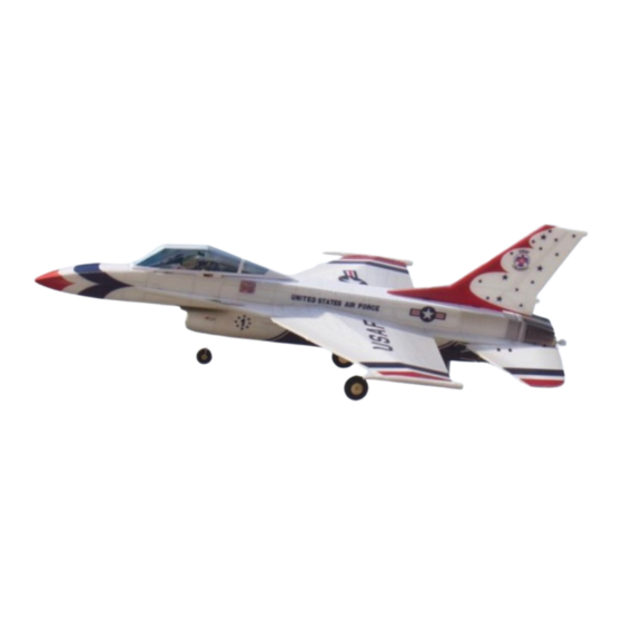
F16 Thunderbirds
Assembly Instructions
Important notification
1.The model is supplied with UFO and 502 glue. UFO is for bonding foam parts, and 502 for
bonding wood, carbon fiber and metal parts. 502 glue will cause serious corrosion to foam parts.
2.Please wait for the glue to dry and solidify in each installation step before the next installation.
3.Please avoid using flame to heat the heat shrinkable tube on the model. Electric iron shall be
used for heating.
4.Please use razor blade to remove the parts from the plate. Do not tear the parts by force.
Advertisement

Related Manuals for MinimumRC F16 Thunderbird


Summary of Contents for MinimumRC F16 Thunderbird
- Page 1 F16 Thunderbirds Assembly Instructions Important notification 1.The model is supplied with UFO and 502 glue. UFO is for bonding foam parts, and 502 for bonding wood, carbon fiber and metal parts. 502 glue will cause serious corrosion to foam parts. 2.Please wait for the glue to dry and solidify in each installation step before the next installation.
- Page 2 1. Fuselage internals. 2. Bond the inner structure of the fuselage with 502 glue. 3. Fix the landing-gear steel wires with m1x3 screws .
- Page 3 4. Fix the landing-gear steel wires with m1x3 screws . 5. Motor base parts.
- Page 4 7. Connect the servos to a powered receiver. Bind the receiver with your transmitter to make the servos arms return to their neutral point. Test whether the servos are working correctly, and install the servo arms according to the position shown in the pictur e. Note: Please make sure that the servos have been tested and installed in strict accordance with the following picture.
- Page 5 9. Connect the receiver to the servos. Fix the receiver with Velcro and tie the cable. 10. Fuselage parts.
- Page 6 12. Stick the plastic reinforcing patch on the inner wall of the fuselage. Note that the patch should be 2mm away from the contour edge of the side plate of the fuselage. 13. Fix the wooden fuselage structure with glue. 14.
- Page 7 15. Connect the motor wire to the receiver and test whether the motor is working correctly. 16. Fix the top and bottom strip of the fuselage with glue. 17. Fix the top and bottom strip of the fuselage with glue.
- Page 8 18. Combine the fuselage and paste stickers. 19. Use knife to cut the carbon fiber rod by rolling back and forth. Cut two sections of 26mm length from the 1.5mm diameter carbon fiber rod. 20. All moving tail parts.
- Page 9 21. Fix the limit ring on one end of the carbon fiber rod with glue. 22. Put the shaft sleeve on the carbon fiber rod , do NOT glue it. 23. Insert the tail wing seat into the other end of the carbon fiber rod and fix it with glue at the central opening.
- Page 10 24. Apply glue (alcohol glue) to the outer wall of one end of the shaft sleeve. 25. Insert the rotating shaft into the reserved hole at the tail.
- Page 11 28. Use the end of a screw driver to score through the half-cut line of the wing surface. 29. Attach the wings to the fuselage.
- Page 12 30.Install the vertical tail. 31. Install the horizontal tail. 32. Install the ventral fin and use wooden protractor to determine the installation angle. Wooden part is only used for measurement and d oes not need to be fixed.
- Page 13 33. Insert the copper axle core into the center of the wood wheel core. 34. Glue the tires.
- Page 14 36. Install the wheels and bend the outer end of the steel wire with pointed nose pliers. 37. Install wing tips. 38. Use heat shrinkable tube to connect tail push rod and steel wire clip.
- Page 15 39. Use heat shrinkable tube to connect the pu sh rod and wire clip, then use glue to fix them. 40. Attach the steel wire hooks to the control horns. 41. Attach the wire clips to the servo arms.
- Page 16 42. Cut the carbon rod to proper length and connect the wire hooks with heat shrinkable tubes. 43. Install pushrods on both sides. 44. Use the end of a screw driver to score through the aileron half-cut line of the hatch.
- Page 17 45. Use glue and stickers to fix the shape of the hatch cover. Apply continuous pressure on the side of the hatch cover before the glue solidifies. 46. Install the magnet on the magnet seat of the hatch cover. 47. Install the hatch cover magnet base. Apply continuous pressure on the side of the hatch cover before the glue solidifies.
- Page 18 48. Install the magnet base at the corresponding position of the fuselage. 49. Push the battery into the front of the fuselage. 50. Fix the counterweight patch inside the nose with Velcro to adjust the center of gravity of the aircraft.
-
Page 19: Maiden Flight
51. Center of gravity. Maiden flight ·The active range of all moving tail is 10mm on both sides. ·choose grass land for maiden flight.
Need help?
Do you have a question about the F16 Thunderbird and is the answer not in the manual?
Questions and answers