Table of Contents
Advertisement
Quick Links
www.ti.com
EVM User's Guide: AMC6V704EVM
AMC6V704 Evaluation Module
Description
This EVM features the AMC6V704, a highly integrated
current-output and voltage-output control device
optimized for electroabsorption modulated laser
(EML) applications. The AMC6V704 includes:
•
Four dedicated 12-bit, 200mA, current output
digital-to-analog converters (IDACs)
•
Four dedicated 12-bit voltage output DACs
(VDACs)
•
A dedicated 12-bit, 1-MSPS analog-to-digital
converter (ADC)
The ADC can be used to monitor external and internal
signals. The AMC6V704 also includes supply and
temperature alarm monitors, and a high-precision
internal reference that eliminates the need for an
external reference in most applications.
SLAU943 – JULY 2024
Submit Document Feedback
Get Started
1. Order the EVM on ti.com
2. Download and install the AMC6V704EVM
software.
3. Configure the hardware jumper settings.
4. Connect the USB and external AMC6V704EVM
supplies.
5. Launch the AMC6V704EVM-GUI.
Features
•
Jumpers to evaluate different device configurations
•
Onboard FT4222 controller for SPI or I
communication
Applications
•
Optical module
•
Optical line cards
AMC6V704EVM
Copyright © 2024 Texas Instruments Incorporated
Description
2
C
AMC6V704 Evaluation Module
1
Advertisement
Table of Contents

Subscribe to Our Youtube Channel
Related Manuals for Texas Instruments AMC6V704


Summary of Contents for Texas Instruments AMC6V704
- Page 1 EVM User's Guide: AMC6V704EVM AMC6V704 Evaluation Module Description Get Started This EVM features the AMC6V704, a highly integrated 1. Order the EVM on ti.com current-output and voltage-output control device 2. Download and install the AMC6V704EVM optimized for electroabsorption modulated laser software.
-
Page 2: Kit Contents
Table 1-1 details the contents of the EVM kit. Contact the TI Product Information Center at (972) 644-5580 if any component is missing. Make sure to verify the latest versions of the related software at the Texas Instruments website, www.ti.com. -
Page 3: Electrostatic Discharge Caution
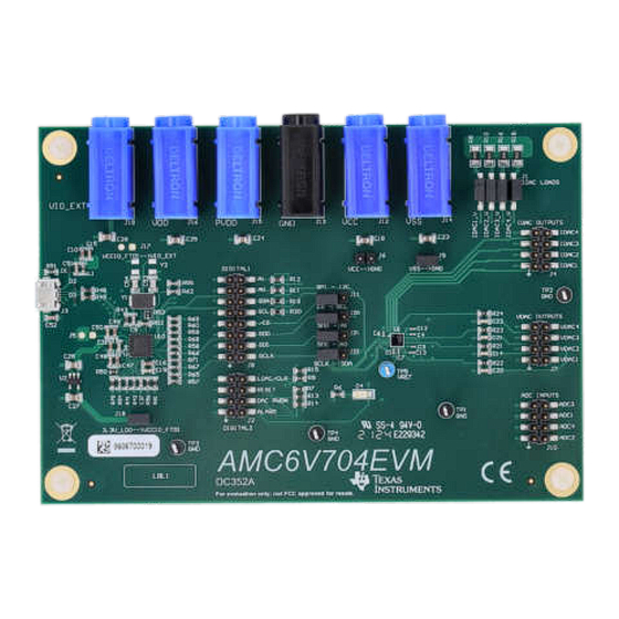
VCC – VSS 1.65V to 3.6V 3.0V to 5.5V 1.5V to 2.2V 2.5V to 5.5V –5.5V to –2.5V 2.5V to 5.5V Figure 2-1. Power Supply Inputs SLAU943 – JULY 2024 AMC6V704 Evaluation Module Submit Document Feedback Copyright © 2024 Texas Instruments Incorporated... -
Page 4: Hardware Description
C and SPI signals USB connector IDAC outputs VDAC outputs Digital Signals ADC inputs TP1, TP2, TP3, TP4 Ground test points VREF test point AMC6V704 Evaluation Module SLAU943 – JULY 2024 Submit Document Feedback Copyright © 2024 Texas Instruments Incorporated... -
Page 5: Software Installation
This section discusses the features of the AMC6V704EVM software and how to use these features. The software provides basic control of all the AMC6V704 registers and functions. 3.2.1 Launching the Software To launch the software, navigate to the Texas Instruments folder in the Start menu, and select the AMC6V704EVM icon. Figure 3-1 shows the Interface Settings window. -
Page 6: Software Features
The menu bar displays the High Level Configuration page with AMC Control, and ADC MUX Control subpages, and the Low Level Configuration page. See the respective device data sheet for detailed AMC6V704 programming instructions before using the GUI. 3.2.2.1 High Level Configuration Page The AMC6V704EVM-GUI has a High Level Configuration page that provides an interface to quickly configure the parameters and relevant register settings for the respective AMC6V704 device. - Page 7 Software Figure 3-3. AMC Control Subpage SLAU943 – JULY 2024 AMC6V704 Evaluation Module Submit Document Feedback Copyright © 2024 Texas Instruments Incorporated...
- Page 8 Figure 3-4 shows the ADC MUX Control subpage. The ADC in the AMC6V704 measures four input pins, as well as the voltages at the IDAC output pins and the current by the VDACs. The ADC MUX Control subpage sets the ADC sequencer controls to select which channels are measured and the order in which the channels are read.
- Page 9 Write Selected or Write Modified buttons are pressed. By default, Immediate Update Mode is selected for the Low Level Configuration page write operations. The AMC6V704 SDO pin must be enabled in the SDO_EN register before reading any device registers. SLAU943 – JULY 2024...
- Page 10 Software www.ti.com Figure 3-6. Low Level Configuration Page Options AMC6V704 Evaluation Module SLAU943 – JULY 2024 Submit Document Feedback Copyright © 2024 Texas Instruments Incorporated...
- Page 11 SDI_A0 SCLK SCLK_SDA VCC=GND 10µF VIO_EXT VIO_EXT 10µF SH-J6 10µF VSS=GND U_DC352_AMC6V704EVM_Hardware PVDD DC352_AMC6V704EVM_Hardware.SchDoc PVDD 10µF DVDD 10µF Figure 4-1. AMC6V704EVM Schematic Page 1 SLAU943 – JULY 2024 AMC6V704 Evaluation Module Submit Document Feedback Copyright © 2024 Texas Instruments Incorporated...
- Page 12 180pF 180pF SDO_A1 A1/SDO ALARM ALARM LDAC_CLR LDAC/CLR VSS1 DAC_PWDN PWDWN VSS2 RESET RESET 0.01uF 0.01uF AMC6V704YBHR VREF Figure 4-3. AMC6V704EVM Schematic Page 3 AMC6V704 Evaluation Module SLAU943 – JULY 2024 Submit Document Feedback Copyright © 2024 Texas Instruments Incorporated...
- Page 13 Figure 4-4. AMC6V704EVM PCB Top Layer Layout Figure 4-5. AMC6V704EVM PCB Mid Layer 1 Layout (Ground Plane) Figure 4-6. AMC6V704EVM PCB Mid Layer 2 Layout (Power Layer) SLAU943 – JULY 2024 AMC6V704 Evaluation Module Submit Document Feedback Copyright © 2024 Texas Instruments Incorporated...
- Page 14 Figure 4-7. AMC6V704EVM PCB Mid Layer 3 Layout (Signal Layer) Figure 4-8. AMC6V704EVM PCB Mid Layer 4 Layout (Ground Plane) Figure 4-9. AMC6V704EVM PCB Bottom Layer Layout AMC6V704 Evaluation Module SLAU943 – JULY 2024 Submit Document Feedback Copyright © 2024 Texas Instruments Incorporated...
- Page 15 Ferrite Bead, 600Ω at 100MHz, 1A, 0603 782633601 Wurth Elektronik R1, R2, R3, R4 301Ω RES, 301, 0.5%, 0.1W, 0603 0603 RT0603DRE07301RL Yageo America SLAU943 – JULY 2024 AMC6V704 Evaluation Module Submit Document Feedback Copyright © 2024 Texas Instruments Incorporated...
- Page 16 Low-Dropout Regulator, DBV0005A DBV0005A TLV74133PDBVR Texas Instruments (SOT-23-5) USB2.0 to QuadSPI/I2C Bridge IC, VQFN-32 VQFN-32 FT4222HQ-D-R FTDI Crystal, 12MHz, 18pF, SMD ABM3 ABM3-12.000MHZ-D2Y-T Abracon Corporation AMC6V704 Evaluation Module SLAU943 – JULY 2024 Submit Document Feedback Copyright © 2024 Texas Instruments Incorporated...
-
Page 17: Additional Information
Newer revisions can be available from the TI web site at https:// www.ti.com, or call the Texas Instruments Literature Response Center at (800) 477-8924 or the Product Information Center at (972) 644-5580. When ordering, identify the document by both title and literature number. - Page 18 STANDARD TERMS FOR EVALUATION MODULES Delivery: TI delivers TI evaluation boards, kits, or modules, including any accompanying demonstration software, components, and/or documentation which may be provided together or separately (collectively, an “EVM” or “EVMs”) to the User (“User”) in accordance with the terms set forth herein.
- Page 19 www.ti.com Regulatory Notices: 3.1 United States 3.1.1 Notice applicable to EVMs not FCC-Approved: FCC NOTICE: This kit is designed to allow product developers to evaluate electronic components, circuitry, or software associated with the kit to determine whether to incorporate such items in a finished product and software developers to write software applications for use with the end product.
- Page 20 www.ti.com Concernant les EVMs avec antennes détachables Conformément à la réglementation d'Industrie Canada, le présent émetteur radio peut fonctionner avec une antenne d'un type et d'un gain maximal (ou inférieur) approuvé pour l'émetteur par Industrie Canada. Dans le but de réduire les risques de brouillage radioélectrique à...
- Page 21 www.ti.com EVM Use Restrictions and Warnings: 4.1 EVMS ARE NOT FOR USE IN FUNCTIONAL SAFETY AND/OR SAFETY CRITICAL EVALUATIONS, INCLUDING BUT NOT LIMITED TO EVALUATIONS OF LIFE SUPPORT APPLICATIONS. 4.2 User must read and apply the user guide and other available documentation provided by TI regarding the EVM prior to handling or using the EVM, including without limitation any warning or restriction notices.
- Page 22 Notwithstanding the foregoing, any judgment may be enforced in any United States or foreign court, and TI may seek injunctive relief in any United States or foreign court. Mailing Address: Texas Instruments, Post Office Box 655303, Dallas, Texas 75265 Copyright © 2023, Texas Instruments Incorporated...
-
Page 23: Important Notice
TI products. TI’s provision of these resources does not expand or otherwise alter TI’s applicable warranties or warranty disclaimers for TI products. TI objects to and rejects any additional or different terms you may have proposed. IMPORTANT NOTICE Mailing Address: Texas Instruments, Post Office Box 655303, Dallas, Texas 75265 Copyright © 2024, Texas Instruments Incorporated...
Need help?
Do you have a question about the AMC6V704 and is the answer not in the manual?
Questions and answers