Table of Contents
Advertisement
Quick Links
www.ti.com
User's Guide
AM273x Evaluation Module
The AM273x EVM is an Evaluation module designed to develop software and evaluate the AM273x Radar
Controller and Processor SoC from Texas Instruments. The AM273x is a multicore SoC designed to provide an
integrated control and processing platform for TI AWR mmWave radar front-end devices in both single-device
and cascaded modes of operation. The signal interface between the AM273x EVM and the AWR2243BOOST
mmWave Radar EVM uses the 60-pin Samtec high density connector.
First.........................................................................................................................................................3
1.1 If You Need Assistance......................................................................................................................................................
1.2 Important Usage Notes......................................................................................................................................................
2 Kit Overview............................................................................................................................................................................
Contents........................................................................................................................................................................3
.....................................................................................................................................................................4
2.3 Component Identification...................................................................................................................................................
Cards..................................................................................................................................................................6
2.5 Security..............................................................................................................................................................................
2.6 Compliance........................................................................................................................................................................
Setup.............................................................................................................................................................................8
Requirements..........................................................................................................................................................8
Buttons......................................................................................................................................................................9
3.3
Switches...........................................................................................................................................................................10
3.4
LEDs.................................................................................................................................................................................11
3.5 Boot Mode Selection........................................................................................................................................................
Description...........................................................................................................................................................14
4.1 Functional Block Diagram................................................................................................................................................
4.2 Memory Interface.............................................................................................................................................................
Interface.............................................................................................................................................................16
4.4 Micro USB Interfaces.......................................................................................................................................................
Interface.....................................................................................................................................................................22
Interface.................................................................................................................................................................23
Interfaces.................................................................................................................................................................25
4.8 JTAG Emulation...............................................................................................................................................................
4.9 SPI Interface....................................................................................................................................................................
Interface..................................................................................................................................................................28
Interface..............................................................................................................................................................29
5
Connectors............................................................................................................................................................................30
5.1 60-Pin High Density (HD) FE Connector-1 (J1)...............................................................................................................
5.4 Debug Connector 60-Pin (J7)..........................................................................................................................................
5.5 External Clock Option (J13, J1).......................................................................................................................................
7 Revision History...................................................................................................................................................................
A Rev. C Design Changes.......................................................................................................................................................
Figure 2-2. AM273x EVM Bottom Component Identification.......................................................................................................
SPRUIY1B - NOVEMBER 2020 - REVISED FEBRUARY 2024
Submit Document Feedback
ABSTRACT
Table of Contents
(J11)..............................................................................................................31
(J19)............................................................................................................................................33
PCB........................................................................................................................................36
List of Figures
Identification.............................................................................................................4
Copyright © 2024 Texas Instruments Incorporated
Table of Contents
3
3
3
4
7
7
13
14
15
17
27
28
30
34
35
37
38
5
AM273x Evaluation Module
1
Advertisement
Table of Contents

Related Manuals for Texas Instruments AM273 Series


Summary of Contents for Texas Instruments AM273 Series
-
Page 1: Table Of Contents
The AM273x EVM is an Evaluation module designed to develop software and evaluate the AM273x Radar Controller and Processor SoC from Texas Instruments. The AM273x is a multicore SoC designed to provide an integrated control and processing platform for TI AWR mmWave radar front-end devices in both single-device and cascaded modes of operation. - Page 2 Table A-2. McASP Mux Select..............................38 Table A-3. eCAP Mux Select..............................Trademarks ™ is a trademark of Texas Instruments. All trademarks are the property of their respective owners. AM273x Evaluation Module SPRUIY1B – NOVEMBER 2020 – REVISED FEBRUARY 2024 Submit Document Feedback...
-
Page 3: Preface: Read This First
AM273x EVM • Micro USB cable • Ethernet Cable • Samtec coax micro ribbon cable (HQCD-030-02.00-SEU-TBR-1) • Spacers, screws, and washers SPRUIY1B – NOVEMBER 2020 – REVISED FEBRUARY 2024 AM273x Evaluation Module Submit Document Feedback Copyright © 2024 Texas Instruments Incorporated... -
Page 4: Key Features
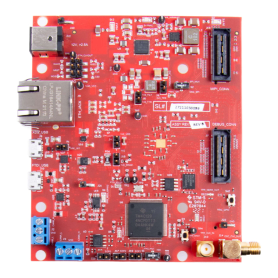
One button and LED for basic user interface • 12V power jack to power the board 2.3 Component Identification Figure 2-1. AM273x EVM Top Component Identification AM273x Evaluation Module SPRUIY1B – NOVEMBER 2020 – REVISED FEBRUARY 2024 Submit Document Feedback Copyright © 2024 Texas Instruments Incorporated... -
Page 5: Figure 2-2. Am273X Evm Bottom Component Identification
Kit Overview Figure 2-2. AM273x EVM Bottom Component Identification SPRUIY1B – NOVEMBER 2020 – REVISED FEBRUARY 2024 AM273x Evaluation Module Submit Document Feedback Copyright © 2024 Texas Instruments Incorporated... -
Page 6: Daughter Cards
AM273x Series microcontroller. Daughter cards are add-on boards that follow a pin-out standard created by Texas Instruments. The TI and third-party ecosystem of daughter cards greatly expands the peripherals and potential applications that you can easily explore with the AM273x EVM. -
Page 7: Security
TIFS-MCU and SBL need to be signed with active customer key 2.6 Compliance All components selected meet RoHS and REACH compliance. SPRUIY1B – NOVEMBER 2020 – REVISED FEBRUARY 2024 AM273x Evaluation Module Submit Document Feedback Copyright © 2024 Texas Instruments Incorporated... -
Page 8: Board Setup
Indication of nRESET pin. If LED is glowing, the device is out of reset 5V_FE Power indicator for 5V FE connectors For further information on the TMDS273GPEVM LEDs, please see Section 3.4. AM273x Evaluation Module SPRUIY1B – NOVEMBER 2020 – REVISED FEBRUARY 2024 Submit Document Feedback Copyright © 2024 Texas Instruments Incorporated... -
Page 9: Push Buttons
PMICOUT_3V3. When idle (not pushed), GPIO_28 (net GPIO_28 MSS_GPIO_28) is pulled to ground via a 10 kilo ohm resistor. SPRUIY1B – NOVEMBER 2020 – REVISED FEBRUARY 2024 AM273x Evaluation Module Submit Document Feedback Copyright © 2024 Texas Instruments Incorporated... -
Page 10: Switches
DNP resistors R5, R61, R167, and R176 must be populated to bring the MSS_SPIB interface out to the J16 header. AM273x Evaluation Module SPRUIY1B – NOVEMBER 2020 – REVISED FEBRUARY 2024 Submit Document Feedback Copyright © 2024 Texas Instruments Incorporated... -
Page 11: Leds
Board Setup 3.4 LEDs Figure 3-4. AM273x EVM LEDs SPRUIY1B – NOVEMBER 2020 – REVISED FEBRUARY 2024 AM273x Evaluation Module Submit Document Feedback Copyright © 2024 Texas Instruments Incorporated... -
Page 12: Table 3-5. Led Information
Glows if there is any HW error in the AM273x NERR_OUT device. Yellow WRMRST Open drain fail safe warm reset signal. Green GPIO_2 Glows when the GPIO_2 is logic-1. AM273x Evaluation Module SPRUIY1B – NOVEMBER 2020 – REVISED FEBRUARY 2024 Submit Document Feedback Copyright © 2024 Texas Instruments Incorporated... -
Page 13: Boot Mode Selection
SOP2 (J17) SOP1 (J18) SOP0 (J20) Dev Management/UART Mode (SOP mode 5) Functional/QSPI Mode (SOP mode 4) Figure 3-5. SOP Jumpers SPRUIY1B – NOVEMBER 2020 – REVISED FEBRUARY 2024 AM273x Evaluation Module Submit Document Feedback Copyright © 2024 Texas Instruments Incorporated... -
Page 14: Hardware Description
Hardware Description www.ti.com 4 Hardware Description 4.1 Functional Block Diagram Figure 4-1. AM273x Functional Block Diagram AM273x Evaluation Module SPRUIY1B – NOVEMBER 2020 – REVISED FEBRUARY 2024 Submit Document Feedback Copyright © 2024 Texas Instruments Incorporated... -
Page 15: Memory Interface
Pins A0, A1, and A2 configure the device address. The WP pin is the Write Protect input. When pulled high, this pin prevents write operations. Figure 4-3. Board ID EEPROM SPRUIY1B – NOVEMBER 2020 – REVISED FEBRUARY 2024 AM273x Evaluation Module Submit Document Feedback Copyright © 2024 Texas Instruments Incorporated... -
Page 16: Ethernet Interface
Ethernet RJ45 Mag-Jack connector, and Table 4-1 provides the connector pin details. Figure 4-4. Ethernet Interface Block Diagram Figure 4-5. Ethernet PHY Schematic AM273x Evaluation Module SPRUIY1B – NOVEMBER 2020 – REVISED FEBRUARY 2024 Submit Document Feedback Copyright © 2024 Texas Instruments Incorporated... -
Page 17: Micro Usb Interfaces
Micro USB connector J8 provides access to the JTAG, MSS_UARTA, and MSS_UARTB interfaces of the AM273x via the XDS110 emulator. SPRUIY1B – NOVEMBER 2020 – REVISED FEBRUARY 2024 AM273x Evaluation Module Submit Document Feedback Copyright © 2024 Texas Instruments Incorporated... -
Page 18: Figure 4-7. Ftdi Usb Block Diagram
Figure 4-7. FTDI USB Block Diagram Table 4-2. J10 Connector Pin Pin Number Description Pin Number Description FTDI_VBUS FTDI_USBD_N FTDI_USBD_P FTDI_USBID AM273x Evaluation Module SPRUIY1B – NOVEMBER 2020 – REVISED FEBRUARY 2024 Submit Document Feedback Copyright © 2024 Texas Instruments Incorporated... -
Page 19: Figure 4-8. Ftdi Usb Connector
FT4232HL USB to UART bridge. By default the 93LC46B contains the power up data for the FT4232HL to boot into a UART configuration. SPRUIY1B – NOVEMBER 2020 – REVISED FEBRUARY 2024 AM273x Evaluation Module Submit Document Feedback Copyright © 2024 Texas Instruments Incorporated... -
Page 20: Figure 4-9. Xds Usb Interface Block Diagram
Figure 4-9. XDS USB Interface Block Diagram Table 4-3. J8 Connector Pin Pin Number Description Pin Number Description XDSET_VBUS XDSET_D_N XDSET_D_P XDSET_ID AM273x Evaluation Module SPRUIY1B – NOVEMBER 2020 – REVISED FEBRUARY 2024 Submit Document Feedback Copyright © 2024 Texas Instruments Incorporated... -
Page 21: Figure 4-10. Xds Usb Connector
When the USB is connected to the PC, the device manager recognizes two XDS110 COM ports under Ports (COM and LPT). XDS110 debug probe and data port are detected under Texas Instruments Debug Probes. If the PC is unable to recognize the above COM ports, then install the EMU pack available at the following link: https://software-dl.ti.com/ccs/esd/documents/xdsdebugprobes/emu_xds_software_package_download.html... -
Page 22: I2C Interface
– Not available on the AM273x EVM by default • RCSS_I2CB: – Not available on the AM273x EVM by default AM273x Evaluation Module SPRUIY1B – NOVEMBER 2020 – REVISED FEBRUARY 2024 Submit Document Feedback Copyright © 2024 Texas Instruments Incorporated... -
Page 23: Uart Interface
One DSP Subsystem Module (DSS_UARTA) – DSS_UARTA_RX and DSS_UARTA_TX are accessible through the FTDI USB port (J10) via the FT4232HL UART - USB Bridge. SPRUIY1B – NOVEMBER 2020 – REVISED FEBRUARY 2024 AM273x Evaluation Module Submit Document Feedback Copyright © 2024 Texas Instruments Incorporated... -
Page 24: Figure 4-12. Uart Interface
Hardware Description www.ti.com Figure 4-12. UART Interface AM273x Evaluation Module SPRUIY1B – NOVEMBER 2020 – REVISED FEBRUARY 2024 Submit Document Feedback Copyright © 2024 Texas Instruments Incorporated... -
Page 25: Can Interfaces
(TCAN1042HGVDRQ1). These can be directly wired to the CAN bus. Figure 4-13. CAN-A Interface Block Diagram Figure 4-14. CAN-A Schematic SPRUIY1B – NOVEMBER 2020 – REVISED FEBRUARY 2024 AM273x Evaluation Module Submit Document Feedback Copyright © 2024 Texas Instruments Incorporated... -
Page 26: Figure 4-15. Can-B Interface Block Diagram
(TCAN1042HGVDRQ1). These can be directly wired to the CAN bus. Figure 4-15. CAN-B Interface Block Diagram Figure 4-16. CAN-B Schematic AM273x Evaluation Module SPRUIY1B – NOVEMBER 2020 – REVISED FEBRUARY 2024 Submit Document Feedback Copyright © 2024 Texas Instruments Incorporated... -
Page 27: Jtag Emulation
'MIPI,' the signals are routed to the MIPI 60 Header (J19) and 60 Pin Debug Header (J7). When S1 is set to 'XDS,' the signals are routed to the emulator and XDS USB port (J8). Figure 4-17. JTAG Emulation Block Diagram SPRUIY1B – NOVEMBER 2020 – REVISED FEBRUARY 2024 AM273x Evaluation Module Submit Document Feedback Copyright © 2024 Texas Instruments Incorporated... -
Page 28: Spi Interface
PHY by default. Please refer to Figure 4-5 for more detail on the Ethernet PHY design. AM273x Evaluation Module SPRUIY1B – NOVEMBER 2020 – REVISED FEBRUARY 2024 Submit Document Feedback Copyright © 2024 Texas Instruments Incorporated... -
Page 29: Epwm Interface
MSS_EPWMA0 is routed to pin 6 of the 60 pin debug header. Figure 4-19. ePWM Debug Header Pin Please see Section 5.4 for further detail on the Debug Connector pinout. SPRUIY1B – NOVEMBER 2020 – REVISED FEBRUARY 2024 AM273x Evaluation Module Submit Document Feedback Copyright © 2024 Texas Instruments Incorporated... -
Page 30: Connectors
Table 5-1. J1 Connector Pin Pin Number Description Pin Number Description RCSS_SPIA_CS RCSS_SPIA_CLK RCSS_SPIA_HOSTINT RCSS_SPIA_PICO RCSS_SPIA_POCI NERRIN_FE1 HW_SYNC_FE1 CSI2_RX0_3P SOP0_FE1 CSI2_RX0_3N SOP1_FE1 SOP2_FE1 CSI2_RX0_2P AM273x Evaluation Module SPRUIY1B – NOVEMBER 2020 – REVISED FEBRUARY 2024 Submit Document Feedback Copyright © 2024 Texas Instruments Incorporated... -
Page 31: 60-Pin High Density (Hd) Fe Connector-2 (J11)
(NRST, NERR, WRMRST, REFCLK, SOPs). This can be connected to the AWR2243BOOST EVM board to interface with the second front end radar device in cascade configuration. Figure 5-2. High Density FE Connector-2 Schematic SPRUIY1B – NOVEMBER 2020 – REVISED FEBRUARY 2024 AM273x Evaluation Module Submit Document Feedback Copyright © 2024 Texas Instruments Incorporated... -
Page 32: Table 5-2. J11 Connector Pin
NERRIN_FE2 HW_SYNC_FE2 CSI2_RX1_3P SOP0_FE2 CSI2_RX1_3N SOP1_FE2 SOP2_FE2 CSI2_RX1_2P WRMRST_FE2 CSI2_RX1_2N REFCLK_FE2 CSI2_RX1_CLKP CSI2_RX1_CLKN CSI2_RX1_1P I2CB_SDA CSI2_RX1_1N I2CB_SCL CSI2_RX1_0P CSI2_RX1_0N nRESET_FE2 AM273x Evaluation Module SPRUIY1B – NOVEMBER 2020 – REVISED FEBRUARY 2024 Submit Document Feedback Copyright © 2024 Texas Instruments Incorporated... -
Page 33: Mipi 60-Pin Connector (J19)
MIPI_RTCK MIPI_TRSTPD MIPI_JTAG_NRST MIPI_VREF MIPI_TRACE_CLK MIPI_DBG_DETECT MIPI_TRACE_CTL MIPI_TRACE0 MIPI_TRACE1 MIPI_TRACE2 MIPI_TRACE3 MIPI_TRACE4 MIPI_TRACE5 MIPI_TRACE6 MIPI_TRACE7 MIPI_TRACE8 MIPI_TRACE9 MIPI_TRACE10 MIPI_TRACE11 MIPI_TRACE12 SPRUIY1B – NOVEMBER 2020 – REVISED FEBRUARY 2024 AM273x Evaluation Module Submit Document Feedback Copyright © 2024 Texas Instruments Incorporated... -
Page 34: Debug Connector 60-Pin (J7)
Pin Number Description XREF_CLK0 MSS_EPWMA0 MSS_SPIB_CS0 MSS_SPIB_CLK MSS_SPIA_HOSTIRQ MSS_SPIB_PICO MSS_SPIB_POCI 3.3V PULL_UP XREF_CLK1 EMU_TCK RCSS_GPIO_49 EMU_TDI GPADC1 EMU_TMS GPADC2 EMU_TDS AM273x Evaluation Module SPRUIY1B – NOVEMBER 2020 – REVISED FEBRUARY 2024 Submit Document Feedback Copyright © 2024 Texas Instruments Incorporated... -
Page 35: External Clock Option (J13, J1)
To enable an external clock from the J1 connector, the R281 resistor must be populated on board. Refer to the AM273x data sheet for external clock specifications. SPRUIY1B – NOVEMBER 2020 – REVISED FEBRUARY 2024 AM273x Evaluation Module Submit Document Feedback Copyright © 2024 Texas Instruments Incorporated... -
Page 36: Mechanical Mounting Of The Pcb
The AM273x EVM is designed to interface with the DCA1000 EVM on Debug Connector (J7). Figure 6-3 shows how the AM273x EVM can be connected to the DCA1000 EVM. AM273x Evaluation Module SPRUIY1B – NOVEMBER 2020 – REVISED FEBRUARY 2024 Submit Document Feedback Copyright © 2024 Texas Instruments Incorporated... -
Page 37: Revision History
Changes from Revision * (November 2020) to Revision A (October 2022) Page • Added Rev C. Design Changes section to detail revision changes from Rev B to Rev C........38 SPRUIY1B – NOVEMBER 2020 – REVISED FEBRUARY 2024 AM273x Evaluation Module Submit Document Feedback Copyright © 2024 Texas Instruments Incorporated... -
Page 38: A Rev. C Design Changes
An additional single pole double throw switch was added to choose between the McASP-A CLK return signal and the eCAP AM273x Evaluation Module SPRUIY1B – NOVEMBER 2020 – REVISED FEBRUARY 2024 Submit Document Feedback Copyright © 2024 Texas Instruments Incorporated... - Page 39 STANDARD TERMS FOR EVALUATION MODULES Delivery: TI delivers TI evaluation boards, kits, or modules, including any accompanying demonstration software, components, and/or documentation which may be provided together or separately (collectively, an “EVM” or “EVMs”) to the User (“User”) in accordance with the terms set forth herein.
- Page 40 www.ti.com Regulatory Notices: 3.1 United States 3.1.1 Notice applicable to EVMs not FCC-Approved: FCC NOTICE: This kit is designed to allow product developers to evaluate electronic components, circuitry, or software associated with the kit to determine whether to incorporate such items in a finished product and software developers to write software applications for use with the end product.
- Page 41 www.ti.com Concernant les EVMs avec antennes détachables Conformément à la réglementation d'Industrie Canada, le présent émetteur radio peut fonctionner avec une antenne d'un type et d'un gain maximal (ou inférieur) approuvé pour l'émetteur par Industrie Canada. Dans le but de réduire les risques de brouillage radioélectrique à...
- Page 42 www.ti.com EVM Use Restrictions and Warnings: 4.1 EVMS ARE NOT FOR USE IN FUNCTIONAL SAFETY AND/OR SAFETY CRITICAL EVALUATIONS, INCLUDING BUT NOT LIMITED TO EVALUATIONS OF LIFE SUPPORT APPLICATIONS. 4.2 User must read and apply the user guide and other available documentation provided by TI regarding the EVM prior to handling or using the EVM, including without limitation any warning or restriction notices.
-
Page 43: Evm
Notwithstanding the foregoing, any judgment may be enforced in any United States or foreign court, and TI may seek injunctive relief in any United States or foreign court. Mailing Address: Texas Instruments, Post Office Box 655303, Dallas, Texas 75265 Copyright © 2023, Texas Instruments Incorporated... - Page 44 TI products. TI’s provision of these resources does not expand or otherwise alter TI’s applicable warranties or warranty disclaimers for TI products. TI objects to and rejects any additional or different terms you may have proposed. IMPORTANT NOTICE Mailing Address: Texas Instruments, Post Office Box 655303, Dallas, Texas 75265 Copyright © 2024, Texas Instruments Incorporated...
Need help?
Do you have a question about the AM273 Series and is the answer not in the manual?
Questions and answers