Ruijie Reyee RG-RAP72Pro Manual
Implementation cookbook
Hide thumbs
Also See for Reyee RG-RAP72Pro:
- Installation manual (32 pages) ,
- Configuration manual (211 pages)

Related Manuals for Ruijie Reyee RG-RAP72Pro


Summary of Contents for Ruijie Reyee RG-RAP72Pro
- Page 1 Ruijie Reyee RG-RAP72Pro Access Point Implementation Cookbook Document Version: V1.0 Date: August 12, 2024 Copyright © 2024 Ruijie Networks...
- Page 2 Ruijie Networks reserves the right to modify the content of the document without any notice or prompt. This manual is designed merely as a user guide. Ruijie Networks has tried its best to ensure the accuracy and reliability of the content when compiling this manual, but it does not guarantee that the content of the manual is completely free of errors or omissions, and all the information in this manual does not constitute any explicit or implicit warranties.
-
Page 3: Preface
Intended Audience This document is intended for: Network engineers Technical support and servicing engineers Network administrators Technical Support The official website of Ruijie Reyee: https://reyee.ruijie.com Technical Support Website: https://reyee.ruijie.com/en-global/support Case Portal: https://www.ruijienetworks.com/support/caseportal Community: https://community.ruijienetworks.com... - Page 4 Instruction An alert that contains additional or supplementary information that if not understood or followed will not lead to serious consequences. Specification An alert that contains a description of product or version support. Instruction This manual is used to guide users to understand the product, install the product, and complete the configuration. ...
- Page 5 Overview This cookbook consists of multiple independent volumes, introducing the installation, deployment, and web- based configuration of the RG-RAP72Pro access point, including: 01- Installation Guide 02- ReyeeOS 2.301 Configuration Guide...
-
Page 6: Table Of Contents
Contents Preface ..............................I 1 Overview ............................1 1.1 About the RG-RAP72Pro ......................1 1.2 Package Contents........................1 1.3 Product Appearance ........................2 1.3.2 Front Panel ........................2 1.3.3 Rear Panel ........................3 1.4 Technical Specifications ......................4 1.5 Power Supply Technical Specifications ..................7 1.6 Cooling ............................ - Page 7 2.3 Tools ............................10 3 Installing the AP..........................12 3.1 Before You Begin ........................12 3.2 Safety Precautions During Installation ..................12 3.3 Installing the AP ........................13 3.4 Removing the AP ........................15 3.5 Bundling Cables ........................16 3.6 Checklist After Installation ....................... 16 4 Debugging ............................
- Page 8 7.1 Connectors and Media ......................21 7.1.1 100/1000/2.5GBASE-T Ports ..................21 7.2 Cabling Recommendations...................... 23 7.2.1 Requirements for Cable Bend Radius ................. 23 7.2.2 Precautions for Bundling up Cables ................23...
-
Page 9: Overview
RG-RAP72Pro Installation Guide Overview Overview About the RG-RAP72Pro The RG-RAP72Pro access point (AP) is a powerful Wi-Fi 7 5040 Mbps dual-band ceiling AP designed for indoor scenarios such as offices, hotels, and schools. Featuring multiple advanced technologies, this AP can deliver high-speed, stable, and secure Wi-Fi connectivity to meet the diverse needs of users. -
Page 10: Product Appearance
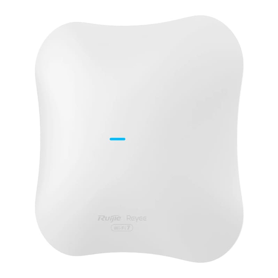
RG-RAP72Pro Installation Guide Overview Product Appearance Figure 1-1 Appearance 1.3.2 Front Panel Figure 1-2 Front Panel Table 1-2 LEDs Status Description Solid blue The device is working properly. The device is not receiving power. -
Page 11: Rear Panel
RG-RAP72Pro Installation Guide Overview Status Description Fast blinking blue The device is starting up. Blinking blue (one blink per 2 The device is not connected to the Internet. seconds) Possible cases: The device is resetting. Blinking blue The device is recovering. twice Caution Do not power off the device when the LED is in this state. -
Page 12: Technical Specifications
RG-RAP72Pro Installation Guide Overview Table 1-3 Components on the Rear Panel Component Description DC power connector Supplies power to the AP, with a power supply specification of DC 12 V Reset button Press and hold for less than 2 seconds: Restart the device. Press and hold for more than 5 seconds: Restore the device to factory settings. - Page 13 RG-RAP72Pro Installation Guide Overview 11a/g: –82 dBm (6 Mbps), –74 dBm (24 Mbps), –70 dBm (36 Mbps), –65 dBm (54 Mbps) 11n: 20MHz: –82 dBm (MCS0), –64 dBm (MCS7) 11n: 40MHz: –79 dBm (MCS0), –61 dBm (MCS7) 11ac: 20MHz: –82 dBm (MCS0), –59 dBm (MCS8) 11ac: 40MHz: –79 dBm (MCS0), –54 dBm (MCS8) 11ac: 80MHz: –76 dBm (MCS0), –51 dBm (MCS9) 11ac: 160MHz: –73 dBm (MCS0), –48 dBm (MCS9)
- Page 14 RG-RAP72Pro Installation Guide Overview 5150 to 5350 MHz, EIRP ≤ 23 dBm ○ 5470 to 5725 MHz, EIRP ≤ 30 dBm ○ 5725 to 5825 MHz, EIRP ≤ 30 dBm ○ Indonesia: 2400 to 2483.5 MHz, EIRP ≤ 27 dBm ○...
-
Page 15: Power Supply Technical Specifications
RG-RAP72Pro Installation Guide Overview Power Supply Technical Specifications The RG-RAP72Pro can be powered by the DC power supply or PoE. When a DC power adapter is used for power supply, the power adapter should have a voltage of 12 V and a current of 2.5 A or higher. -
Page 16: Preparing For Installation
RG-RAP72Pro Installation Guide Preparing for Installation Preparing for Installation Safety Guidelines Note To avoid personal injury and device damage, review the safety guidelines in this chapter before you begin the installation. The following safety precautions may not include all the potentially hazardous situations. 2.1.1 Safety Precautions ... -
Page 17: Installation Site Requirements
RG-RAP72Pro Installation Guide Preparing for Installation Make sure that the AP is powered off when you cut off the power supply. Do not place the AP in a wet position, and keep it away from liquid. Keep the AP far away from grounding or lightning protection devices for power equipment. ... -
Page 18: Emi
RG-RAP72Pro Installation Guide Preparing for Installation ≥ 3 μm ≤2.4 x 10 Particles/m ≥ 5 μm ≤1.3 x 10 Particles/m Apart from dust, the salt, acid, and sulfide in the air of the equipment room must meet strict requirement. These harmful substances will accelerate metal corrosion and component aging. - Page 19 RG-RAP72Pro Installation Guide Preparing for Installation Note This device is delivered without a toolkit. Prepare the preceding tools by yourself.
-
Page 20: Installing The Ap
RG-RAP72Pro Installation Guide Installing the AP Installing the AP The RG-RAP72Pro must be installed indoors, and used in a fixed place. Caution Before installing the AP, make sure that you have carefully read the requirements described in Chapter 2. Before You Begin Before installing the RG-RAP72Pro, carefully plan and arrange the installation location, networking mode, power supply, and cabling. -
Page 21: Installing The Ap
RG-RAP72Pro Installation Guide Installing the AP Installing the AP Note In an indoor environment, a ceiling-mounted AP offer broader antenna radiation coverage compared to a wall-mounted one. Hence, ceiling mounting is the preferred option. The schematic diagram provided is for reference purposes only. The actual product should be installed based on its physical specifications and design. - Page 22 RG-RAP72Pro Installation Guide Installing the AP Caution The plane deviation of the wall in a specific area should be within 2 mm (0.08 in.), and the recommended torque for installation is 4 kgf.cm. In case of uneven installation site, please mount the AP on a protruding wall. (3) Connect cables according to the actual networking.
-
Page 23: Removing The Ap
RG-RAP72Pro Installation Guide Installing the AP Caution Before securing the AP to the mounting plate, connect the cables first. The slots on the back of the AP must be aligned with and slid into the square feet on the mounting plate. Do not press the slots into the square feet by force. -
Page 24: Bundling Cables
RG-RAP72Pro Installation Guide Installing the AP (2) Slide down the AP as indicated by the arrow. Bundling Cables Caution Bundle the cable in a visually pleasing way. Make sure that the fibers at the connectors have natural bends or bends of large radius. ... -
Page 25: Debugging
Verify the LED status. After the AP is powered on, check whether the SSID (@Ruijie-mXXXX for multiple devices or @Ruijie-sXXXX for a single device) can be searched by a mobile phone or other wireless devices. Logging In to the Web GUI (1) Power on the PC and configure the local connection attribute on the PC. -
Page 26: Monitoring And Maintenance
RG-RAP72Pro Installation Guide Monitoring and Maintenance Monitoring and Maintenance Monitoring When the RG-RAP72Pro is operating, you can monitor the device running status by observing the LED. Maintenance If the hardware is faulty, please contact the local distributor. -
Page 27: Troubleshooting
Check whether the LED is normal. Check whether cables are properly connected with ports. Contact Ruijie technical support to check whether hardware faults exist. Common Faults 6.2.1 The Status LED Is Off After the AP Is Powered On ... - Page 28 RG-RAP72Pro Installation Guide Troubleshooting (3) Verify that the AP is correctly configured. (4) Move the client device closer to the AP.
-
Page 29: Appendix
RG-RAP72Pro Installation Guide Appendix Appendix Connectors and Media 7.1.1 100/1000/2.5GBASE-T Ports The 2.5GBASE-T/1000BASE-T/100BASE-TX port is 2.5 Gbps/1000 Mbps/100 Mbps port that supports auto MDI/MDIX Crossover. Compliant with the IEEE 802.3bz standard, 2500BASE-T requires a Category 6 (Cat 6) or Category 5e (Cat 5e) 100-ohm UTP or STP (recommended) cable with a maximum distance of 100 meters (328 feet). - Page 30 RG-RAP72Pro Installation Guide Appendix Figure 7-2 show feasible connections of the straight-through and crossover twisted pairs for a 100BASE-TX port. Figure 7-2 100BASE-TX Twisted Pair Connection...
-
Page 31: Cabling Recommendations
RG-RAP72Pro Installation Guide Appendix Cabling Recommendations During installation, route cable bundles upward or downward along the sides of the rack depending on the actual situation in the equipment room. All cable connectors used for transit should be placed at the bottom of the cabinet rather than be exposed outside of the cabinet. - Page 32 RG-RAP72Pro Installation Guide Appendix without sharp corners. The metal hole traversed by cables should have a smooth and fully rounding surface or an insulated lining. Use cable ties to bundle up cables properly. Do not connect two or more cable ties to bundle up cables. ...
- Page 33 RG-RAP72Pro Installation Guide Appendix The power cords connecting moving parts such as grounding cables should be reserved with some access after being assembled to avoid suffering tension or stress. After the moving part is installed, the remaining cable part should not touch heat sources, sharp corners, or sharp edges. If heat sources cannot be avoided, high-temperature cables should be used.
- Page 34 Contents Preface ..............................I 1 Fast Internet Access ........................... 1 1.1 Configuration Environment Requirements ................1 1.1.1 PC ..........................1 1.2 Default Configuration ......................... 1 1.3 Login to Web Interface ....................... 1 1.3.1 Connecting to the Access Point ..................1 1.3.2 Configuring the IP Address of the Management Client ..........
- Page 35 1.8.1 Management Page for Wi-Fi 7 Products ..............11 2 Network Monitoring ..........................1 2.1 Viewing the Network Information ....................1 2.2 Adding Network Devices ......................3 2.2.1 Wired Connection ......................3 2.2.2 AP Mesh ......................... 5 2.3 Managing Network Devices ..................... 13 2.4 Configuring Network Planning ....................
- Page 36 3.10 Configuring Layer-3 Roaming ....................33 3.11 Configuring Client Isolation ....................34 3.12 Configuring 802.11r ....................... 34 3.13 Configuring a Guest Wi-Fi ..................... 35 3.13.1 Overview ........................35 3.13.2 Configuration Steps ....................35 3.14 Configuring Wireless Rate Limiting ..................36 3.14.1 Overview ........................
- Page 37 3.24.3 Configuring Traffic Load Balancing ................64 3.25 Wireless Authentication ......................66 3.25.1 Overview ........................66 3.25.2 Configuring One-click Login on Ruijie Cloud ............. 66 3.25.3 Configuring Voucher Authentication on Ruijie Cloud ..........71 3.25.4 Configuring Account Authentication on Ruijie Cloud ..........79 3.25.5 Configuring SMS Authentication on Ruijie Cloud ............
- Page 38 3.26.4 Viewing Wired User List ................... 108 4 Network Settings ..........................109 4.1 Switching Work Mode ......................109 4.1.1 Work Mode ......................... 109 4.1.2 Self-Organizing Network Discovery ................109 4.1.3 Configuration Steps ....................109 4.2 Configuring Internet Connection Type (IPv4) ................ 111 4.3 Configuring Internet Connection Type (IPv6) ................
- Page 39 4.14 Configuring Port Flow Control ..................... 124 4.15 Configuring ARP Binding ..................... 124 4.16 Configuring LAN Ports ......................125 4.17 IPv6 Settings ........................126 4.17.1 Overview ........................127 4.17.2 IPv6 Basic ........................ 127 4.17.3 IPv6 Address Assignment Methods ................. 127 4.17.4 Enabling IPv6 ......................
- Page 40 6.5.1 Overview ........................144 6.5.2 Global Configuration ....................144 6.5.3 View/Group/Community/User Access Control ............146 6.5.4 SNMP Service Typical Configuration Examples ............154 6.5.5 Configuring Trap Service ................... 159 6.5.6 Trap Service Typical Configuration Examples ............163 6.6 Configuring Reboot ........................ 166 6.6.1 Rebooting the Master Device ..................
- Page 41 6.13 Configuring Cloud Service ....................175 6.13.1 Overview ........................175 6.13.2 Configuration Steps ....................175 6.13.3 Unbinding Cloud Service ..................177 7 Network Diagnosis Tools ........................ 178 7.1 Network Check ........................178 7.2 Network Tools ........................179 7.3 Alerts ............................180 7.4 Fault Collection ........................
-
Page 42: Fast Internet Access
Wireless Connection On a mobile phone or laptop, search for wireless network @Ruijie-SXXXX (XXXX is the last four digits of the MAC address of each device). In this mode, you do not need to set the IP address of the management Client, and you can skip the operation in 1.3.2 Configuring the IP Address of the Management... -
Page 43: Configuring The Ip Address Of The Management Client
Fast Internet Access Configuration Guide 1.3.2 Configuring the IP Address of the Management Client Configure an IP address for the management client in the same network segment as the default IP address of the device (The default device IP address is 10.44.77.254, and the subnet mask is 255.255.255.0.) so that the management client can access the device. -
Page 44: Work Mode
Fast Internet Access Configuration Guide If you forget the IP address or password, hold down the Reset button on the device panel for more than 5 seconds when the device is connected to the power supply to restore factory settings. After restoration, you can use the default IP address and password to log in. -
Page 45: Wireless Repeater Mode
Fast Internet Access Configuration Guide Caution After switching to the router mode, the device's LAN IP address will change to 192.168.120.1. Please obtain an IP address automatically for your management client and enter 10.44.77.254 into the address bar of the browser to log in to web interface again. -
Page 46: Configuration Steps
Fast Internet Access Configuration Guide 1.5.2 Configuration Steps 1. Add a Device to Network You can manage and configure all devices in the network in batches by default. Please verify the device count and network status before configuration. Note New devices will join in a network automatically after being powered on. You only need to verify the device count. - Page 47 Fast Internet Access Configuration Guide If a new device is detected not in the network, click Add to My Network and enter its management password to add the device manually. 2. Creating a Network Project (1) Click Start Setup to configure the Internet connection type and Wi-Fi network. ...
- Page 48 Fast Internet Access Configuration Guide (2) Click Next. On the page that is displayed, set the project name and management password. Project Name: Identify the network project where the device is located. Management Password: The password is used for logging in to the management page. Click Finish.
-
Page 49: Configuration Steps
Fast Internet Access Configuration Guide The device can access the Internet now. Bind the device with a Ruijie Cloud account for remote management. Follow the instruction to log in to Ruijie Cloud for further configuration. Note If your device is not connected to the Internet, click Exit to exit the configuration wizard. -
Page 50: Configuration Steps
Fast Internet Access Configuration Guide Caution No Ethernet cable is required in the wireless repeater mode. The wireless network stability can be affected by many factors. Therefore, the wired connection is recommended. 1.7.2 Configuration Steps (1) Connect the device to a power supply without connecting an Ethernet cable to the uplink port, and click Start Setup. - Page 51 Fast Internet Access Configuration Guide (4) Set the SSID and password and click Save. Then, the Wi-Fi network will be restarted. (5) Set the country/region code and time zone, and click Save.
-
Page 52: Introduction To The Web Interface
Fast Internet Access Configuration Guide Introduction to the Web Interface To facilitate flexible device management, the Web page displays different system configuration menus in different work modes. For details about the work mode, see Switching Work Mode. As to the RG-RAP72Pro model, please refer to 1.8.1 Management Page for Wi-Fi 7 Products. - Page 53 Fast Internet Access Configuration Guide Network–Wide Mode Local Device Mode To access the local device mode for the configuration and management of a single device, perform the following steps: ○ Method 1: Click the device name in the One Device menu and then click Config. ○...
- Page 54 Fast Internet Access Configuration Guide 2. Disabling Self-Organizing Network Discovery If a device is in standalone mode, you can configure and manage only the currently logged in device. The web interface displays the configuration menu of a single device on the left side.
- Page 55 Fast Internet Access Configuration Guide...
-
Page 56: Network Monitoring
Network Monitoring Configuration Guide Network Monitoring Choose Network-Wide > Workspace > Topology. The Overview webpage displays the current network topology, real-time uplink and downlink flow, networking status, and the number of users. The quick access to network and device settings is also provided on the Overview webpage. - Page 57 Network Monitoring Configuration Guide Click the egress gateway to view real-time traffic information of the device. Click the device in the topology to view the operating status and configuration of the device and configure the device functions. The hostname is set to the product model by default. You can click to modify the hostname.
-
Page 58: Adding Network Devices
Network Monitoring Configuration Guide The update time of the topology is displayed at the bottom left corner. Click Refresh to update the topology to the latest status. Please wait for a few minutes for the update. Adding Network Devices 2.2.1 Wired Connection (1) If a new device is connected to the device in the network through wired connection, a prompt message will... - Page 59 Network Monitoring Configuration Guide of devices that are not in SON is displayed under the Devices at the top left corner of the page. Click Handle to add the device to the current network. (2) Go to the Network List page, click Other Network to select the target device and click Add to My Network. If the target device is not configured yet, you can add the device directly without a password.
-
Page 60: Ap Mesh
Network Monitoring Configuration Guide 2.2.2 AP Mesh 1. Overview After being powered on and enabled with Mesh (see 3.21 Enabling Reyee Mesh for details), a Mesh-capable new AP can be paired with other Mesh-capable wireless devices on the target network through multiple ways. Then the AP will be synchronized its Wi-Fi configuration with other devices automatically. - Page 61 Network Monitoring Configuration Guide The master device must be properly configured. Otherwise, AP mesh failure may occur due to constant channel scanning. The new AP must be in factory status. It can be scanned only when the live network is enabled with Mesh (see 3.21 Enabling Reyee Mesh for details).
- Page 62 Network Monitoring Configuration Guide (6) Click View Details following the icon to obtain information about the uplink device and RSSI. 4. Configuration Steps for Search-based Pairing Caution Uplink device is an AP or EGW router. The master device must be properly configured. Otherwise, AP mesh failure may occur due to constant channel scanning.
- Page 63 Network Monitoring Configuration Guide (3) On the AP Mesh page, click Scan to scan devices that are not connected to the network via an Ethernet cable. (4) Select the APs to be added and click Add to My Network. No more than eight APs are allowed at a time. Wait until network merging finishes.
- Page 64 Network Monitoring Configuration Guide (5) Check the topology on the Physical Topology page to make sure that the new AP has connected to the uplink device in wireless mode. (6) Power off the new AP and install it as planned. (7) Log in to the web interface of a device on the target network.
- Page 65 Network Monitoring Configuration Guide 5. Configuration Steps for Wired Pairing Caution Uplink device is an AP, EG router, or EGW router. The new AP must be in factory status. It can be scanned only when the live network is enabled with Mesh (see 3.21 Enabling Reyee Mesh for details).
- Page 66 Network Monitoring Configuration Guide (6) Click View Details following the icon to obtain information about the uplink device and RSSI. 6. Enabling WAN Port The WAN port works as the wired uplink port of the AP by default. For the AP added to the target network through Mesh pairing, the WAN port is disabled by default.
- Page 67 Network Monitoring Configuration Guide (2) Choose Config > Advanced > Enable WAN, toggle on Enable, and click Save. 7. Querying Mesh APs and Mesh Details (1) Log in to the web interface of a device on the target network. (2) Query Mesh APs. ...
-
Page 68: Managing Network Devices
Network Monitoring Configuration Guide (3) Query Mesh networking details. In Network-Wide mode, choose Devices > AP. Select the target AP, and click View Details in the Relay Information column to obtain the Mesh networking details. Managing Network Devices You can view information of all devices on the network. You can configure and manage all devices on the network by simply logging in to only one device on the network. - Page 69 Network Monitoring Configuration Guide Click Manage to configure the selected device. Click Select to select an offline device, and click Delete Offline to remove the selected device from the list and the topology.
-
Page 70: Configuring Network Planning
Network Monitoring Configuration Guide Configuring Network Planning Choose Network-Wide > Workspace > Network Planning. Click the SSID to edit the Wi-Fi configuration. For details, see Chapter 3 Wi-Fi Network Settings. -
Page 71: Configuring Wired Vlan
Network Monitoring Configuration Guide 2.4.1 Configuring Wired VLAN Choose Network-Wide > Workspace > Network Planning. On the Network Planning page, click Add Wired VLAN. - Page 72 Network Monitoring Configuration Guide Alternatively, you can select an existing wired VLAN and click Setup to edit the VLAN. (1) Configure the VLAN ID, address pool server, and DHCP pool. The gateway is configured as the address pool server by default to assign IP addresses to clients. If an access switch exists in the network, you can select the access switch as the address pool server.
- Page 73 Network Monitoring Configuration Guide (2) Select the target switch in the topology and all member ports in the VLAN, and click Next. (3) Please confirm the delivered configurations and click Save. The configurations will take effect after a few minutes.
-
Page 74: Configuring Wi-Fi Vlan
Network Monitoring Configuration Guide 2.4.2 Configuring Wi-Fi VLAN Choose Network-Wide > Workspace > Network Planning. On the Network Planning page, click Add Wi-Fi LAN. Alternatively, you can select an existing wireless VLAN and click Setup to edit the VLAN. - Page 75 Network Monitoring Configuration Guide (1) Configure the SSID, Wi-Fi password and band. Click Expand to expand the advanced settings and set the parameters. Then, click Next. (2) Configure the VLAN ID, address pool server and DHCP pool. The gateway is configured as the address pool server by default to assign IP addresses to clients.
- Page 76 Network Monitoring Configuration Guide...
-
Page 77: Wi-Fi Network Settings
Configuration Guide Wi-Fi Network Settings Wi-Fi Network Settings Note Wi-Fi network settings covers the Wi-Fi settings of the currently logged in devices and the management of all wireless devices in the network. In Network mode, the Wi-Fi network settings are synchronized to all wireless devices in the network. - Page 78 Configuration Guide Wi-Fi Network Settings (3) Click to create a new group. Up to 8 groups can be added. You can click to edit the group name and click to delete the group. The default group cannot be deleted and its name cannot be edited. (4) Click the group name on the left part to view all devices in this group.
-
Page 79: Adding A Wi-Fi Network
Configuration Guide Wi-Fi Network Settings Adding a Wi-Fi Network (1) Go to the page for configuration. Method 1: Choose Network-Wide > Workspace > Wireless > Wi-Fi > Wi-Fi List. Method 2: Choose One-Device > Config > WLAN > Wi-Fi > Wi-Fi List. (2) Click Add Wi-Fi. - Page 80 Configuration Guide Wi-Fi Network Settings (4) Click advanced Settings to configure more Wi-Fi parameters. After configuration, click OK. After the Wi-Fi is added, a client can detect the SSID, and the Wi-Fi information is displayed in the Wi-Fi list. Table 3-1 Wi-Fi Configuration Parameters Parameter Description...
- Page 81 Configuration Guide Wi-Fi Network Settings Parameter Description Set the band used by the Wi-Fi signal. The options are 2.4 GHz and 5 GHz. The 5 GHz band provides faster network transmission rate and less interference than the 2.4 GHz band, but is inferior to the 2.4 GHz band in terms of signal coverage Band range and wall penetration performance.
-
Page 82: Configuring Ssid And Wi-Fi Password
Configuration Guide Wi-Fi Network Settings Parameter Description After this function is enabled, the device sends game packets preferentially, XPress providing more stable wireless network for games. After this function is enabled, clients keep their IP addresses unchanged when Layer-3 Roaming associating with the same Wi-Fi. -
Page 83: Managing Wi-Fi Networks
Configuration Guide Wi-Fi Network Settings Managing Wi-Fi Networks (1) Go to the configuration page. Method 1: Choose Network-Wide > Workspace > Wireless > Wi-Fi > Wi-Fi List. Method 2: Choose One-Device > Config > WLAN > Wi-Fi > Wi-Fi List. (2) Click manage to batch manage Wi-Fi networks. - Page 84 Configuration Guide Wi-Fi Network Settings ○ Batch disable Wi-Fi networks: Select the desired Wi-Fi networks, and click Disable. ○ Batch delete Wi-Fi networks: Select the desired Wi-Fi networks, and click Delete. (4) Click Exit to exit Wi-Fi network batch management.
-
Page 85: Hiding The Ssid
Configuration Guide Wi-Fi Network Settings Hiding the SSID 3.5.1 Overview Hiding the SSID can prevent unauthorized clients from accessing the Wi-Fi network and enhance network security. After this function is enabled, the mobile phone or PC cannot search out the SSID. Instead, you have to manually enter the correct SSID and Wi-Fi password. -
Page 86: Configuring Wi-Fi Band
Configuration Guide Wi-Fi Network Settings Configuring Wi-Fi Band (1) Go to the page for configuration. Method 1: Choose Network-Wide > Workspace > Wireless > Wi-Fi > Wi-Fi List. Select the Wi-Fi network, and click Edit. Method 2: Choose One-Device > Config > WLAN > Wi-Fi > Wi-Fi List. Select the Wi-Fi network, and click Edit. -
Page 87: Configuring Wi-Fi 6
Configuration Guide Wi-Fi Network Settings (2) Click to expand advanced settings, turn on Band Steering in the expanded settings, and click OK. After the function is enabled, the client supporting 5 GHz selects the 5G Wi-Fi network preferentially. Configuring Wi-Fi 6 Caution The function takes effect only on APs supporting the IEEE 802.11ax protocol. -
Page 88: Configuring Layer-3 Roaming
Configuration Guide Wi-Fi Network Settings Configuring Wi-Fi 7 Caution This configuration takes effect only on APs that support the IEEE 802.11be protocol. Clients also need to support the IEEE 802.11be protocol in order to experience high-speed Internet access brought by Wi-Fi 7. Disable this feature if the client does not support Wi-Fi 7. -
Page 89: Configuring Client Isolation
Configuration Guide Wi-Fi Network Settings 3.11 Configuring Client Isolation (1) Go to the page for configuration. Method 1: Choose Network-Wide > Workspace > Wireless > Wi-Fi > Wi-Fi List. Select the Wi-Fi network, and click Edit. Method 2: Choose One-Device > Config > WLAN > Wi-Fi > Wi-Fi List. Select the Wi-Fi network, and click Edit. -
Page 90: Configuring A Guest Wi-Fi
Configuration Guide Wi-Fi Network Settings and click Edit. Method 2: Choose One-Device > Config > WLAN > Wi-Fi > Wi-Fi List. Select the Wi-Fi network, and click Edit. (2) Click advanced Settings. Enable 802.11r, and click OK. 3.13 Configuring a Guest Wi-Fi 3.13.1 Overview This Wi-Fi network is provided for guests and is disabled by default. -
Page 91: Overview
Configuration Guide Wi-Fi Network Settings 3.14 Configuring Wireless Rate Limiting 3.14.1 Overview The device supports four rate limiting modes: client-based rate limiting, SSID-based rate limiting, AP-based rate limiting, and packet-based rate limiting. For the same client, if multiple rate limiting modes are configured, the priority order is as follows: client-based rate limiting >... - Page 92 Configuration Guide Wi-Fi Network Settings (1) Enable Wireless Rate Limiting. (2) Click Add. In the dialog box that appears, set the MAC address and uplink and downlink rate limit values of the client, and click OK.
- Page 93 Configuration Guide Wi-Fi Network Settings Configuring SSID-based Rate Limiting Method 1: Choose Network-Wide > Workspace > Wireless > Rate Limiting > SSID-based Rate Limiting. (1) Enable Wireless Rate Limiting. (2) Click Edit in the Action column of the target SSID. In the dialog box that appears, set the uplink and downlink rate limit modes and values, and click OK.
- Page 94 Configuration Guide Wi-Fi Network Settings Configuring AP-based Rate Limiting Choose Network-Wide > Workspace > Wireless > Rate Limiting > AP-based Rate Limiting. (1) Enable Wireless Rate Limiting. (2) Set the uplink and downlink rate limit modes to Rate Limit Per User, configure the rate limit values, and click Configuring Packet-based Rate Limiting Choose Network-Wide >...
-
Page 95: Overview
Configuration Guide Wi-Fi Network Settings 3.15 Configuring Wi-Fi Blocklist or Allowlist 3.15.1 Overview You can configure the global or SSID-based blocklist and allowlist. The MAC address supports full match and OUI match. Wi-Fi blocklist: Clients in the Wi-Fi blocklist are prevented from accessing the Internet. Clients that are not added to the Wi-Fi blocklist are free to access the Internet. - Page 96 Configuration Guide Wi-Fi Network Settings and not allowed to access the Wi-Fi network. The global blocklist and allowlist settings take effect on all Wi-Fi networks of the access point. 2. Configuring an SSID-based Blocklist/Allowlist Choose Network-Wide > Workspace > Wireless > Blocklist and Allowlist > SSID-Based Blocklist/Allowlist. Select a target Wi-Fi network from the left column, select the blocklist or allowlist mode and click Add to configure a blocklist or allowlist client.
-
Page 97: Overview
Configuration Guide Wi-Fi Network Settings 3.16 Optimizing Wi-Fi Network 3.16.1 Overview The device detects the surrounding wireless environment and selects the appropriate configuration upon power- on. However, network stalling caused by wireless environment changes cannot be avoided. You can optimize the network with one single click, analyze the wireless environment around the access point and select appropriate parameters. -
Page 98: Configuring Global Radio Settings
Configuration Guide Wi-Fi Network Settings 3.16.3 Configuring Global Radio Settings 1. Optimizing the Channel Width Choose Network-Wide > Workspace > Wireless > Radio Setting. A network with a lower channel width is more stable, while a network with a higher channel width is susceptible to interference. - Page 99 Configuration Guide Wi-Fi Network Settings 2. Configuring the Multicast Rate Choose Network-Wide > Workspace > Wireless > Radio Setting. If the multicast rate is too high, the packet loss rate of multicast packets may increase. If the multicast rate is too low, the radio interface may become busy.
- Page 100 Configuration Guide Wi-Fi Network Settings If the access point is associated with too many clients, it will have a lower performance, affecting user experience. After you configure the threshold, new clients over the threshold will not be allowed to access the Wi-Fi network. You can lower the threshold if there is requirement for bandwidth per client.
-
Page 101: Configuring Standalone Radio Settings
Configuration Guide Wi-Fi Network Settings Caution In the self-organizing network mode, the kick-off threshold settings will be synchronized to all devices in the network. 3.16.4 Configuring Standalone Radio Settings Go to the configuration page. Method 1: Choose One-Device > Config > WLAN > Radio Setting. ... - Page 102 Configuration Guide Wi-Fi Network Settings 1. Optimizing the Radio Channel Method 1: Choose One-Device > Config > WLAN > Radio Setting. Method 2: Choose Network-Wide > Devices > Manage > Config > WLAN > Radio Setting. Choose the best channel identified by Wi-Fi Moho or other Wi-Fi scanning App. Click Save to make the configuration take effect immediately.
- Page 103 Configuration Guide Wi-Fi Network Settings 2. Optimizing the Transmit Power Method 1: Choose One-Device > Config > WLAN > Radio Setting. Method 2: Choose Network-Wide > Devices > Manage > Config > WLAN > Radio Setting. A greater transmit power indicates a larger coverage and brings stronger interference to surrounding wireless routers.
- Page 104 Configuration Guide Wi-Fi Network Settings 4. Configuring Access Threshold Method 1: Choose One-Device > Config > WLAN > Radio Setting. Method 2: Choose Network-Wide > Devices > Manage > Config > WLAN > Radio Setting. When the wireless signal of the end user is lower than the access threshold set on the device, the client cannot detect the wireless signal of the device.
- Page 105 Configuration Guide Wi-Fi Network Settings When the wireless signal of the end user is lower than the response RSSI threshold configured on the device, the client cannot detect the wireless signal of the device. The smaller the response RSSI threshold is configured, the less the environmental factors interfere with the AP.
-
Page 106: Configuring Wio
Configuration Guide Wi-Fi Network Settings 3.16.5 Configuring WIO Choose Network-Wide > Workspace > WLAN Optimization. Select the optimization mode. Then, click OK to optimize the wireless network. Caution WIO is supported only in the self-organizing network mode. The client may be offline during the optimization process. The configuration cannot be rolled back once optimization starts. - Page 107 Configuration Guide Wi-Fi Network Settings Parameter Description In this mode, external interference and bandwidth are considered. A deep optimization is performed to optimize channel, power, and management frame power. Click to expand Advanced Settings to configure the scanning time, channel bandwidth and channels. Scanning time: Indicates the time for scanning channels during the optimization.
- Page 108 Configuration Guide Wi-Fi Network Settings...
- Page 109 Configuration Guide Wi-Fi Network Settings After the optimization starts, please be patient and wait for the optimization to complete. After optimization is completed, you can click Cancel Optimization to restore the optimized RF parameters to their default values. Click Back to Home to perform wireless optimization again.
-
Page 110: Configuring Wi-Fi Roaming Optimization (802.11K/V)
Configuration Guide Wi-Fi Network Settings Click Optimization Record to view the details of the latest optimization. You are advised to set a scheduled task to optimize the wireless network in the early hours of the morning or when the network is idle. 3.16.6 Configuring Wi-Fi Roaming Optimization (802.11k/v) Choose Network-Wide... - Page 111 Configuration Guide Wi-Fi Network Settings Choose the optimization mode. Click Enable and the Wi-Fi roaming is further optimized through the 802.11k/v protocol. Smart clients compliant with 802.11k/v can switch to the APs with better signal and faster speed during the roaming process, ensuring high-speed wireless connectivity. To ensure smart roaming effect, the WLAN environment will be auto scanned when Wi-Fi roaming optimization is first enabled.
-
Page 112: Configuring Igmp Snooping
Configuration Guide Wi-Fi Network Settings 3.17 Configuring IGMP Snooping 3.17.1 Overview 1. IGMP Snooping IGMP snooping allows switches to listen for and analyze IGMP (Internet Group Management Protocol) messages in order to determine which switch ports are connected to hosts that are interested in specific multicast groups. -
Page 113: Configuring Healthy Mode
Configuration Guide Wi-Fi Network Settings 3.18 Configuring Healthy Mode Go to the configuration page: Method 1: Choose Network-Wide > Workspace > Wireless > Wi-Fi > Healthy Mode. Method 2: Choose One-Device > Config > WLAN > Wi-Fi > Healthy Mode. Select Device Group from the drop-down list box. -
Page 114: Configuring Wireless Schedule
Configuration Guide Wi-Fi Network Settings 3.20 Configuring Wireless Schedule (1) Go to the page for configuration. Method 1: Choose Network-Wide > Workspace > Wireless > Wi-Fi > Wi-Fi List. Select the Wi-Fi network, and click Edit. Method 2: Choose One-Device >... -
Page 115: Client Association
Configuration Guide Wi-Fi Network Settings Note method 2 is supported only when the AP is the master device. When a client accesses a Wi-Fi network, the message "No Internet connection" or "The Wi-Fi is not connected to the Internet" may be displayed. The possible cause is that the client's operating system introduces an Internet detection mechanism. -
Page 116: Configuring Client Association
Configuration Guide Wi-Fi Network Settings After certain smart home devices are associated with a remote AP, they are unable to re-associate with a nearby AP, resulting in poor user experience and significant delays. With the Intelligent Association feature enabled, clients can dynamically select the access point for association, eliminating issues related to poor user experience caused by remote associations. -
Page 117: Configuring Ap Load Balancing
Configuration Guide Wi-Fi Network Settings Caution The Forced Association feature may cause the client to go offline or fail to associate with the AP. Therefore, exercise caution when performing this configuration. 3.24 Configuring AP Load Balancing 3.24.1 Overview The AP load balancing function is used to balance the load of APs in the wireless network. When APs are added to a load balancing group, clients will automatically associate with the APs with light load when the APs in the group are not load balanced. -
Page 118: Configuring Client Load Balancing
Configuration Guide Wi-Fi Network Settings 3.24.2 Configuring Client Load Balancing Choose Network-Wide > Workspace > Wireless > Load Balancing. Click Add. In the dialog box that appears, set Type to Client Load Balancing, and configure Group Name, Members, and Rule. -
Page 119: Configuring Traffic Load Balancing
Configuration Guide Wi-Fi Network Settings Table 3-4 Client Load Balancing Configuration Parameters Parameter Description Group Name Enter the name of the AP load balancing group. Type Select Client Load Balancing. Configure a detailed load balancing rule, including the maximum number of clients allowed to associate with an AP, the difference between the currently associated client count and client count on the AP with the lightest load, and the number of attempts to the AP with full load. - Page 120 Configuration Guide Wi-Fi Network Settings Table 3-5 Traffic Load Balancing Configuration Parameters Parameter Description Group Name Enter the name of the AP load balancing group. Type Select Traffic Load Balancing. Configure a detailed load balancing rule, including the maximum traffic allowed on an AP, the difference between the current traffic and the traffic on the AP with the lightest load, and the number of attempts to the AP with full load.
-
Page 121: Wireless Authentication
To use the wireless authentication function, ensure that the AP is added to Ruijie Cloud and is online. Then, configure a portal template on Ruijie Cloud and apply it to a specific SSID. When STAs connect to this SSID and access the network, the AP allows STAs added to the authentication-free lists configured on the web interface (excluding those added to the MAC address blocklist) to access the network without authentication. - Page 122 Configuration Guide Wi-Fi Network Settings (4) Configure basic information of the portal template. Table 3-6 Portal Template Configuration Parameters Parameter Description Portal Name Indicates the name of a captive portal template. Select One-click Login, which indicates login without the username and password.
- Page 123 Configuration Guide Wi-Fi Network Settings Table 3-7 Portal Page Configuration Parameters Parameter Description Logo Select whether to display the logo image. Logo Image When Logo is set to Image, upload the logo picture or select the default logo. Logo Position Select the logo position (Upper, Middle, or Lower).
- Page 124 Configuration Guide Wi-Fi Network Settings Parameter Description When Background is set to Image, upload the background image or select Background Image the default image. When Background is set to Solid Color, configure the background color. The Background Mask Color default value is #ffffff. Welcome Message Select the welcome message with the image or text.
- Page 125 Configuration Guide Wi-Fi Network Settings Table 3-8 Captive Portal Configuration Parameters Parameter Description Policy Name Indicates the name of a captive portal template. Indicates the authentication mode to which the captive portal applies: Inner: Cloud-based authentication. The built-in authentication server in the public cloud is used for authentication.
-
Page 126: Configuring Voucher Authentication On Ruijie Cloud
1. Configuring a Portal Template with the Authentication Mode Set to Voucher (1) Log in to Ruijie Cloud, choose Project > Configuration > Auth & Accounts > Authentication > Captive Portal, and select a network that needs to configure wireless authentication. - Page 127 Configuration Guide Wi-Fi Network Settings (4) Configure basic information of the portal template. Table 3-9 Portal Template Configuration Parameters Parameter Description Portal Name Indicates the name of a captive portal template. Login Options Select Voucher, which indicates login with a random eight-digit password. Show Balance Page Indicates the available duration, time, or data after portal authentication.
- Page 128 Configuration Guide Wi-Fi Network Settings Table 3-10 Portal Page Configuration Parameters Parameter Description Logo Select whether to display the logo image.
- Page 129 Configuration Guide Wi-Fi Network Settings Parameter Description When Logo is set to Image, upload the logo picture or select the default logo. Logo Image Logo Position Select the logo position (Upper, Middle, or Lower). Background Select the background with the image or the solid color. When Background is set to Image, upload the background image or select Background Image the default image.
- Page 130 Configuration Guide Wi-Fi Network Settings 2. Configuring Policy Info Configure basic information of the policy info to add captive portal. After the configuration, click OK for the configurations to take effect. Note When Encryption Mode is set to a value other than WPA2-Enterprise(802.1x), the Captive Portal page is available.
- Page 131 Click Add Page to customize a portal page. 3. Adding a Voucher (1) Log in to Ruijie Cloud, choose Project > Auth & Accounts > Accounts > User Management, and select a network in this account. (2) Configure a user group.
- Page 132 Configuration Guide Wi-Fi Network Settings Configure user group parameters. After the configuration, click OK. User Group Name: indicates the user group name. Price: indicates the price of the user group. Mark user groups by numeral. The current version has no impact on network usage.
- Page 133 Configuration Guide Wi-Fi Network Settings Maximum upload rate: indicates the maximum upload rate. Maximum download rate: indicates the maximum download rate. Bind MAC on first use: indicates that the MAC address of the first device used will be bound and other devices used by the same user will be prohibited from accessing the Internet.
-
Page 134: Configuring Account Authentication On Ruijie Cloud
1. Configuring a Portal Template with the Authentication Mode Set to Account (1) Log in to Ruijie Cloud, choose Project > Configuration > Auth & Accounts > Authentication > Captive Portal, and select a network that needs to configure wireless authentication. - Page 135 Configuration Guide Wi-Fi Network Settings (4) Configure basic information of the portal template. Table 3-12 Portal Template Configuration Parameters Parameter Description Portal Name Indicates the name of a captive portal template. Select Account, which indicates login with the account and password. Login Options Show Balance Page Indicates the available duration, time, or data after portal authentication.
- Page 136 Configuration Guide Wi-Fi Network Settings...
- Page 137 Configuration Guide Wi-Fi Network Settings Table 3-13 Portal Page Configuration Parameters Parameter Description Logo Select whether to display the logo image. When Logo is set to Image, upload the logo picture or select the default logo. Logo Image Logo Position Select the logo position (Upper, Middle, or Lower).
- Page 138 Configuration Guide Wi-Fi Network Settings Parameter Description Text Color in Box Select the text color in the box. The default value is #ffffff. (6) After the configuration, click OK to save the portal template configurations. 2. Configuring Policy Info Configure basic information of the policy info to add captive portal. After the configuration, click OK for the configurations to take effect.
- Page 139 Click Add Page to customize a portal page. 3. Adding an Account (1) Log in to Ruijie Cloud, choose Project > Auth & Accounts > Accounts > User Management, and select a network in this account. (2) Configure a user group.
- Page 140 Configuration Guide Wi-Fi Network Settings Configure user group parameters. After the configuration, click OK. User Group Name: indicates the user group name. Price: indicates the price of the user group. Mark user groups by numeral. The current version has no impact on network usage.
- Page 141 Configuration Guide Wi-Fi Network Settings Maximum upload rate: indicates the maximum upload rate. Maximum download rate: indicates the maximum download rate. Bind MAC on first use: indicates that the MAC address of the first device used will be bound and other devices used by the same user will be prohibited from accessing the Internet.
-
Page 142: Configuring Sms Authentication On Ruijie Cloud
Click Please select an .xls or .xlsx file to upload the file. After uploading, users are automatically created. 3.25.5 Configuring SMS Authentication on Ruijie Cloud 1. Adding a Twilio Account Prerequisites A Twilio account has been applied for from the Twilio official website (https://www.twilio.com/login). - Page 143 2. Configuring a Portal Template with the Authentication Mode Set to SMS (1) Log in to Ruijie Cloud, choose Project > Configuration > Auth & Accounts > Authentication > Captive Portal, and select a network that needs to configure wireless authentication.
- Page 144 Configuration Guide Wi-Fi Network Settings (4) Configure basic information of the portal template. Table 3-15 Portal Template Configuration Parameters Parameter Description Portal Name Indicates the name of a captive portal template. Select SMS, which indicates login with the phone number and code. Login Options Show Balance Page Indicates the available duration, time, or data after portal authentication.
- Page 145 Configuration Guide Wi-Fi Network Settings...
- Page 146 Configuration Guide Wi-Fi Network Settings Table 3-16 Portal Page Configuration Parameters Parameter Description Logo Select whether to display the logo image. When Logo is set to Image, upload the logo picture or select the default logo. Logo Image Logo Position Select the logo position (Upper, Middle, or Lower).
- Page 147 Configuration Guide Wi-Fi Network Settings Parameter Description Button Text Color Select the button text color. The default value is #ffffff. Link Color Select the link color. The default value is #ffffff. Text Color in Box Select the text color in the box. The default value is #ffffff. (6) After the configuration, click OK to save the portal template configurations.
- Page 148 Configuration Guide Wi-Fi Network Settings Parameter Description Indicates the authentication mode to which the captive portal applies: Inner: Cloud-based authentication. The built-in authentication server in the public cloud is used for authentication. Local: Device-based local authentication and acceleration. Portal pages and Policy Mode accounts in the cloud are synchronized with the device for local authentication and acceleration.
-
Page 149: Configuring Registration On Ruijie Cloud
1. Configuring a Portal Template with the Authentication Mode Set to One-click Login (1) Log in to Ruijie Cloud, choose Project > Configuration > Auth & Accounts > Authentication > Captive Portal, and select a network that needs to configure wireless authentication. - Page 150 Configuration Guide Wi-Fi Network Settings Table 3-18 Portal Template Configuration Parameters Parameter Description Portal Name Indicates the name of a captive portal template. Select One-click Login, which indicates login without the username and password. You can set Access Duration and Access Times Per Day. Login Options Show Balance Page Indicates the available duration, time, or data after portal authentication.
- Page 151 Configuration Guide Wi-Fi Network Settings Table 3-19 Portal Page Configuration Parameters Parameter Description Logo Select whether to display the logo image. Logo Image When Logo is set to Image, upload the logo picture or select the default logo. Logo Position Select the logo position (Upper, Middle, or Lower).
- Page 152 Configuration Guide Wi-Fi Network Settings Parameter Description When Background is set to Image, upload the background image or select Background Image the default image. When Background is set to Solid Color, configure the background color. The Background Mask Color default value is #ffffff. Welcome Message Select the welcome message with the image or text.
- Page 153 Configuration Guide Wi-Fi Network Settings Table 3-20 Captive Portal Configuration Parameters Parameter Description Policy Name Indicates the name of a captive portal template. Indicates the authentication mode to which the captive portal applies: Inner: Cloud-based authentication. The built-in authentication server in the public cloud is used for authentication.
-
Page 154: Configuring An Authentication-Free User List On Web Interface
Configuration Guide Wi-Fi Network Settings Parameter Description Indicates the wired network that requires authentication. Enter the network segment in this field. Network Users connecting to the wired network corresponding to this network segment must be authenticated. This parameter is required if the Authentication Device is Router. Indicates the network name of the Wi-Fi network that requires authentication. - Page 155 Configuration Guide Wi-Fi Network Settings (3) Configure an STA IP address or IP address range. After the configuration, click OK to save the configurations. 2. Configuring an Authentication-Free Public IP Address (1) Choose Network-Wide > Workspace > Wireless > Wireless Auth > Allowlist > IP Allowlist. (2) Click Add to open the configuration page.
- Page 156 Configuration Guide Wi-Fi Network Settings (3) Configure authentication-free websites. After the configuration, click OK. 4. Configuring a MAC Address Allowlist and Blocklist STAs whose MAC addresses are added to the MAC address allowlist can access the network without authentication, and STAs whose MAC addresses are added to the MAC address blocklist are forbidden to access the network.
-
Page 157: Displaying Authenticated Users On Web Interface
The client going offline will not disappear immediately. Instead, the client will stay on the list for three more minutes. 3.25.9 Displaying Authenticated Users on Ruijie Cloud Log in to Ruijie Cloud, choose Project > Network > Clients > Auth Clients, and select a network that needs to display authenticated users. -
Page 158: Configuring 802.1X Authentication
Configuration Guide Wi-Fi Network Settings 3.26 Configuring 802.1X Authentication 3.26.1 Overview IEEE 802.1X is a port-based network access control standard that provides secure access services for LANs. On an IEEE 802 LAN, a user can directly access network resources without authentication and authorization as long as it can connect to a network device. - Page 159 Configuration Guide Wi-Fi Network Settings Enable the Escape SSID and configure parameters such as Escape SSID. Users can temporarily connect to the Escape SSID without a password when the authentication server is unavailable. Toggle on Re-authentication and set the re-authentication interval. The re-authentication function performs periodic user authentication, and users who do not pass the periodic authentication will be disconnected.
- Page 160 Configuration Guide Wi-Fi Network Settings Client Packet Timeout Duration: The time limit for a client to wait for a response from the server. An authentication failure occurs after this time limit expires. The value range is 1 to 65535 seconds. (3) Add a server.
- Page 161 Configuration Guide Wi-Fi Network Settings You can click to add multiple servers to a server group, and click to delete a selected server. Table 3-21 Server Group Configuration Parameters Parameter Description Server group name Name of RADIUS server group Server IP IP address of the RADIUS server.
- Page 162 Configuration Guide Wi-Fi Network Settings Parameter Description Shared Password Shared key of the RADIUS server. The system supports up to five RADIUS servers. A larger value indicates Match Order a higher priority. (4) Configure the server and click Save. Table 3-22 Server Global Configuration Parameters Parameter Description...
-
Page 163: Viewing Wireless User List
Configuration Guide Wi-Fi Network Settings 3.26.3 Viewing Wireless User List When the 802.1X feature is configured globally, and a client is authenticated and connected to the network in a wireless manner, you can view the client in the Wireless User List. Choose Network-Wide >... -
Page 164: Network Settings
Configuration Guide Network Settings Network Settings Note This chapter takes the currently logged in device as an example to describe the entry of each function setting page. If you need to configure other devices in the network, please refer to the following path to enter the configuration page of the corresponding device, and then configure the function: For RG-RAP72Pro, Click Managing Network Devices. - Page 165 Configuration Guide Network Settings AC function switch: If a device works in the router mode and the self-organizing network discovery function is enabled, you can enable or disable the AC function. After the AC function is enabled, the device in the router mode supports the virtual AC function and can manage downlink devices.
-
Page 166: Configuring Internet Connection Type (Ipv4)
Configuration Guide Network Settings Configuring Internet Connection Type (IPv4) Go to the configuration page: Method 1: Choose One-Device > Config > Network > WLAN > WAN. Method 2: Choose Network-Wide > Workspace > Wired > WAN > WAN. Select the Internet connection type after confirming with the ISP. -
Page 167: Configuring Internet Connection Type (Ipv6)
Configuration Guide Network Settings Configuring Internet Connection Type (IPv6) Caution This function is supported when the device works in AP mode. Go to the configuration page: Method 1: Choose One-Device > Config > Network > WLAN > WAN_V6 Settings. ... - Page 168 Configuration Guide Network Settings Click Edit. In the displayed dialog box, enter the IP address and subnet mask, and click OK. Change the IP address of the LAN port. Enter the new IP address in the browser and log in to the device again to configure and manage the device.
-
Page 169: Configuring Repeater Mode
Configuration Guide Network Settings Parameter Description Lease time of the automatically assigned IP addresses. When the lease Lease Time (Min) time expires, devices on the LAN will obtain IP addresses again. Configuring Repeater Mode 4.5.1 Wired Repeater Choose One-Device. Click the device mode, and then choose Config > Network > Work Mode. Connect a network cable from the WAN port (uplink LAN port) of the device to the upper-layer device. - Page 170 Configuration Guide Network Settings Click Wireless Repeater and then click Select. A list of surrounding Wi-Fi signals pops up. A list of nearby 5 GHz Wi-Fi networks is displayed by default. You can switch from 5 GHz to 2.4 GHz band by selecting 2.4G from the drop-down list box.
-
Page 171: Creating A Vlan
Configuration Guide Network Settings ○ If New Wi-Fi is selected, you can set a local Wi-Fi name and password. Clients will search out different Wi-Fi signals. Caution After the configuration is saved, the AP will be disconnected from the Wi-Fi network and needs to connect to the new Wi-Fi network. - Page 172 Configuration Guide Network Settings Go to the configuration page: Method 1: Choose One-Device > Config > Network > LAN > LAN Settings. Method 2: Choose Network-Wide > Workspace > Wired > LAN > LAN Settings. A LAN can be classified into multiple VLANs. Click Add to create a VLAN. Table 4-2 VLAN Configuration Parameters Parameter...
-
Page 173: Configuring Port Vlan
Configuration Guide Network Settings Parameter Description Enable the DHCP server function. After it is enabled, devices on the LAN can automatically obtain IP addresses. After the DHCP service is enabled, you need to configure the start IP DHCP Server address to be assigned, number of IP addresses to be assigned, and address lease term for the DHCP server, and other DHCP server options. -
Page 174: Changing Mac Address
Configuration Guide Network Settings (3) Switch to the Port VLAN tab page and configure VLANs for the port. Click the option box below the port, select the mapping between a VLAN and the port from the drop-down list box, and click Save. ○... -
Page 175: Changing Mtu
Configuration Guide Network Settings Method 2: Choose Network-Wide > Workspace > Wired > WAN > WAN. ISPs may restrict the access of devices with unknown MAC addresses to the Internet for the sake of security. In this case, you can change the MAC address of the WAN port. Click to expand Advanced Settings, enter the MAC address, and click Save. -
Page 176: Configuring Dhcp Server
Configuration Guide Network Settings 4.10 Configuring DHCP Server Caution This function is not supported when the device works in AP mode. 4.10.1 DHCP Server In the router mode, the DHCP server function can be enabled on the device to automatically assign IP addresses to clients so that clients connected to the LAN ports or Wi-Fi network of the device obtain IP addresses for Internet access. -
Page 177: Displaying Online Dhcp Clients
Configuration Guide Network Settings 4.10.3 Displaying Online DHCP Clients Go to the configuration page: Method 1: Choose One-Device > Config > Network > LAN > DHCP Clients. Method 2: Choose Network-Wide > Workspace > Wired > LAN > DHCP Clients. Check information about an online client. -
Page 178: Displaying The Dhcp Static Ip Address List
Configuration Guide Network Settings 4.10.4 Displaying the DHCP Static IP Address List Go to the configuration page: Method 1: Choose One-Device > Config > Network > LAN > Static IP Addresses. Method 2: Choose Network-Wide > Workspace > Wired > LAN > Static IP Addresses. Click Add. -
Page 179: Configuring Self-Healing Mesh
Configuration Guide Network Settings 4.12 Configuring Self-Healing Mesh Choose One-Device > Config > Advanced > Self-Healing Mesh. After Reyee Mesh is enabled, Self-Healing Mesh is automatically switched to Wireless Repeater mode to ensure normal service operation if a fault occurs on the wired link. 4.13 Hardware Acceleration Choose... -
Page 180: Configuring Lan Ports
Configuration Guide Network Settings Choose One-Device > Config > Security > ARP List. ARP mappings can be bound in two ways: (1) Select a dynamic ARP entry in the ARP list and click Bind. You can select multiple entries to be bound at one time and click Bind Selected to bind them. -
Page 181: Ipv6 Settings
Configuration Guide Network Settings In self-organizing network mode, the AP wired port configuration applies to all APs having wired LAN ports on the current network. The configuration applied to APs in LAN Port Settings takes effect preferentially. Click Add to add the AP wired port configuration. For APs, to which no configuration is applied in LAN Port Settings, the default configuration of the AP wired ports will take effect on them. -
Page 182: Overview
Configuration Guide Network Settings 4.17.1 Overview Internet Protocol Version 6 (IPv6) is the next generation IP protocol designed by the Internet Engineering Task Force (IETF) to replace IPv4 and solve the IPv4 problems such as address depletion. 4.17.2 IPv6 Basic IPv6 Address Format IPv6 increases the length of the address from 32 bits in IPv4 to 128 bits, and therefore has a larger address space than IPv4. -
Page 183: Enabling Ipv6
Configuration Guide Network Settings Stateless Address Autoconfiguration (SLAAC): The link local address is generated based on the interface ID, and then the local address is automatically configured based on the prefix information contained in the route advertisement packet. Stateful address autoconfiguration, that is, DHCPv6: DHCPv6 is divided into the following two types: ○... -
Page 184: Configuring The Ipv6 Address For The Wan Port
Configuration Guide Network Settings 4.17.5 Configuring the IPv6 Address for the WAN Port Choose One-Device > Config > Network > IPv6 Address > WAN Settings. Configure the IPv6 address for the WAN port, and click Save. -
Page 185: Configuring The Ipv6 Address For The Lan Port
Configuration Guide Network Settings Table 4-3 WAN Port IPv6 Address Configuration Parameters Parameter Description Specify the method for obtaining an IPv6 address for the WAN port. DHCP/PPPoE: The current device will act as a DHCPv6 client and apply for the IPv6 address/prefix from the upstream network device. - Page 186 Configuration Guide Network Settings Click Edit corresponding to the default VLAN, and fill in a local address of no more than 64 bits in the IPv6 Address/Prefix Length column. This address will also be used as the IPv6 address prefix. IPv6 Assignment specifies the method for assigning IPv6 addresses for clients.
-
Page 187: Viewing Dhcpv6 Clients
Configuration Guide Network Settings Table 4-4 LAN Port IPv6 Address Configuration Parameters Parameter Description Configure the interface from which the prefix is obtained, for example, Subnet Prefix Name WAN_V6. The default value is all interfaces. Configure the length of the subnet prefix. The value ranges from 48 to Subnet Prefix Length Configure the subnet ID in hexadecimal notation. -
Page 188: Configuring The Static Dhcpv6 Address
Configuration Guide Network Settings When the device acts as a DHCPv6 server to assign IPv6 addresses to clients, you can view information about the clients that obtain IPv6 addresses from the device on the current page. The information includes the host name, IPv6 address, remaining lease term, and DHCPv6 Unique Identifier (DUID) of each client. -
Page 189: Configuring The Ipv6 Neighbor List
Configuration Guide Network Settings 4.17.9 Configuring the IPv6 Neighbor List In IPv6, Neighbor Discovery Protocol (NDP) is an important basic protocol. NDP replaces the ARP and ICMP route discovery protocols of IPv4, and supports the following functions: address resolution, neighbor status tracking, duplicate address detection, router discovery, and redirection. -
Page 190: Online Client Management
Configuration Guide Online Client Management Online Client Management Caution When the AP is used as the primary device, clients on the network are only displayed when the AP works in router mode. When the AP is used as a secondary device, the functions presented in the web interface are based on the primary device on the network. - Page 191 Configuration Guide Online Client Management Parameter Description Indicates the access mode of the client, which can be wireless or wired. The SSID SSID and Band and frequency band is displayed when a client is connected wirelessly. The Wi-Fi signal strength of the client and the associated channel. Signal Quality Note This information is displayed only in the wireless online client list.
-
Page 192: Configuring Client Ip Binding
Configuration Guide Online Client Management Configuring Client IP Binding Caution This function is supported only in router mode. Choose Network-Wide > Clients. IP address binding is a security and access control policy that associates a specific IP address with a specific device or user to achieve identity authentication, access control, monitoring, and accounting. -
Page 193: Configuring Client Association
Configuration Guide Online Client Management Unbind an IP address Select the client to be unbound from the list, click Bound, and click OK in the pop-up box. Configuring Client Association Choose Network-Wide > Clients. Caution This function applies only to wireless clients. Select a client in the list and click Associate in the Action column. -
Page 194: Blocking Clients
Configuration Guide Online Client Management Blocking Clients Choose Network-Wide > Clients. An unauthorized client may occupy network bandwidth and pose security risks. You can block specified clients to solve the unauthorized access problem. Caution Client block is available only for wireless clients. ... -
Page 195: Configuring Client Rate Limiting
Configuration Guide Online Client Management Select the target clients, click Block, and click OK in the pop-up box to block the selected clients. Cancel block Choose Network-Wide > Workspace > Wireless > Blocklist/Allowlist > Global Blocklist/Allowlist. Select the client to be removed from the blocklist in the wireless blocklist and click Delete. Configuring Client Rate Limiting Choose Network-Wide >... - Page 196 Configuration Guide Online Client Management Cancel rate limits Click the Wireless tab, click the LimitSpeed column in the table, and click Disable.
-
Page 197: System Settings
Configuration Guide System Settings System Settings PoE Settings Choose One-Device > Config > Advanced > PoE Settings. Set the power mode for the AP to accept power over PoE. In AF mode, the maximum power supported by the device is 15.4 W. In AT mode, the maximum power is 30 W according to the IEEE 802.3at standard. In BT mode, the maximum power is 51 W according to the IEEE 802.3bt standard. -
Page 198: Setting The Session Timeout Duration
Configuration Guide System Settings Setting the Session Timeout Duration Go to the configuration page: In self-organizing network mode: Choose One-Device > Config > System > Login. In standalone mode: Choose System > Login > Session Timeout. If no operation is performed on the Web page within a period of time, the session is automatically disconnected. When you need to perform operations again, enter the password to log in again. -
Page 199: Configuring Snmp
Configuration Guide System Settings Configuring SNMP 6.5.1 Overview The Simple Network Management Protocol (SNMP) is a protocol for managing network devices. Based on the client/server model, it can achieve remote monitoring and control of network devices. SNMP uses a manager and agent architecture. The manager communicates with agents through the SNMP protocol to retrieve information such as device status, configuration details, and performance data. - Page 200 Configuration Guide System Settings SNMP v2c: As an improved version of SNMP v1, SNMP v2c supports richer functions and more complex data types, with enhanced security. SNMP v2c performs better than SNMP v1 in terms of security and functionality, and is more flexible. It can be configured according to different needs. SNMP v3: As the newest version, SNMP v3 supports security mechanisms such as message authentication and encryption compared to SNMP v1 and SNMP v2c.
-
Page 201: View/Group/Community/User Access Control
Configuration Guide System Settings Table 6-1 Global Configuration Parameters Parameter Description SNMP Service Indicates whether SNMP service is enabled. SNMP Version Indicates the SNMP protocol version, including v1, v2c, and v3 versions. Local Port The port range is 1 to 65535. 1-64 characters. - Page 202 Configuration Guide System Settings (2) Configure basic information of a view. Table 6-2 View Configuration Parameters Parameter Description Indicates the name of the view. View Name 1-32 characters. Chinese or full width characters are not allowed. Indicates the range of OIDs included in the view, which can be a single OID or a subtree of OIDs.
- Page 203 Configuration Guide System Settings 2. Configuring v1/v2c Users Overview When the SNMP version is set to v1/v2c, user configuration is required. Note Select the SNMP protocol version, and click Save. The corresponding configuration options will appear on the View/Group/Community/User Access Control page. ...
- Page 204 Configuration Guide System Settings Table 6-3 v1/v2c User Configuration Parameters Parameter Description At least 8 characters. It must contain at least three character categories, including uppercase and lowercase letters, digits, and special characters. Community Name Admin, public or private community names are not allowed. Question marks, spaces, and Chinese characters are not allowed.
- Page 205 Configuration Guide System Settings Note Select the SNMP protocol version, and click Save. The corresponding configuration options will appear on the View/Group/Community/User Access Control page. Configuration Steps Choose Network-Wide > Workspace > Network-Wide > SNMP > View/Group/Community/Client Access Control > SNMP v3 Group List. (1) Click Add in the SNMP v3 Group List pane to create a group.
- Page 206 Configuration Guide System Settings Table 6-4 v3 Group Configuration Parameters Parameter Description Indicates the name of the group. 1-32 characters. Group Name Chinese characters, full-width characters, question marks, and spaces are not allowed. Indicates the minimum security level (authentication and encryption, Security Level authentication but no encryption, no authentication and encryption) of the group.
- Page 207 Configuration Guide System Settings 4. Configuring v3 Users Prerequisites When the SNMP version is set to v3, the v3 group configuration is required. Note Select the SNMP protocol version, and click Save. The corresponding configuration options will appear on the View/Group/Community/User Access Control page.
- Page 208 Configuration Guide System Settings Table 6-5 v3 User Configuration Parameters Parameter Description Username At least 8 characters. It must contain at least three character categories, including uppercase Username and lowercase letters, digits, and special characters. Admin, public or private community names are not allowed. Question marks, spaces, and Chinese characters are not allowed.
-
Page 209: Snmp Service Typical Configuration Examples
Configuration Guide System Settings Parameter Description Encryption protocols supported: DES/AES/AES192/AES256. Encryption password: 8-31 characters. Chinese characters, full-width characters, question marks, and spaces are not allowed. Encryption Protocol, Encrypted It must contain at least three character categories, including uppercase Password and lowercase letters, digits, and special characters. Note: This parameter is mandatory when the security level is authentication and encryption. - Page 210 Configuration Guide System Settings Table 6-6 User Requirement Specification Item Description Included rule: the OID is .1.3.6.1.2.1.1, and the custom view name is View range "system". For SNMP v2c, the custom community name is "Ruijie_com", and the Version default port number is 161. Read &...
- Page 211 Configuration Guide System Settings (3) On the View/Group/Community/Client Access Control interface, enter the SNMP v1/v2c community name. Click Add in the SNMP v1/v2c Community Name List pane. Enter the group name, access mode, and view in the pop-up window. Click OK. 2.
- Page 212 Configuration Guide System Settings Table 6-7 User Requirement Specification Item Description Included rule: the OID is .1.3.6.1.2.1, and the custom view name is View range "public_view". Group name: group Security level: authentication and encryption Group configuration Select public_view for a read-only view. Select public_view for a read &...
- Page 213 Configuration Guide System Settings (3) On the View/Group/Community/Client Access Control interface, add an SNMP v3 group. Click Add in the SNMP v3 Group List pane. Enter the group name and security level on the pop-up window. As this user has read and write permissions, select public_view for read-only and read &...
-
Page 214: Configuring Trap Service
Configuration Guide System Settings 6.5.5 Configuring Trap Service Trap is a notification mechanism of the Simple Network Management Protocol (SNMP) protocol. It is used to report the status and events of network devices to administrators, including device status, faults, performance, configuration, and security management. - Page 215 Configuration Guide System Settings 2. Configuring Trap v1/v2c Users Overview Trap is a notification mechanism that is used to send alerts to administrators when important events or failures occur on devices or services. Trap v1/v2c are two versions in the SNMP protocol for network management and monitoring.
- Page 216 Configuration Guide System Settings Table 6-8 Trap v1/v2c User Configuration Parameters Parameter Description Dest Host IP IP address of the trap peer device. An IPv4 or IPv6 address is supported. Version Number Trap version, including v1 and v2c. Port ID The port range of the trap peer device is 1 to 65535.
- Page 217 Configuration Guide System Settings Prerequisites When the v3 version is selected for the trap service, it is necessary to add a trap v3 user. Configuration Steps Choose Network-Wide > Workspace > Network-Wide > SNMP > Trap Settings. (1) Click Add in the Trap v3 Client List pane to add a trap v3 user. (2) Configure trap v3 user parameters.
-
Page 218: Trap Service Typical Configuration Examples
Configuration Guide System Settings Parameter Description Name of the trap v3 user. At least 8 characters. It must contain at least three character categories, including uppercase Username and lowercase letters, digits, and special characters. Admin, public or private community names are not allowed. Question marks, spaces, and Chinese characters are not allowed. - Page 219 Configuration Guide System Settings According to the user's application scenario, the requirements are shown in the following table: Table 6-10 User Requirement Specification Item Description IP address and port number The destination host IP is 192.168.110.85, and the port number is 166. Version Select the v2c version.
- Page 220 Description IP address and port number The destination host IP is 192.168.110.87, and the port number is 167. Version and user name Select the v3 version and trapv3_ ruijie for the user name. Authentication protocol/authentication password Authentication protocol/password: MD5/Ruijie123 Encryption protocol/encryption...
-
Page 221: Configuring Reboot
Configuration Guide System Settings (2) Click Add in the Trap v3 Client List to add a trap v3 user. (3) Enter the destination host IP address, port number, user name, and other information. Then, click OK. Configuring Reboot Caution Do not cut off power during system reboot to avoid device damage. -
Page 222: Rebooting Local Device
Configuration Guide System Settings device. Click the Reboot button. The master device will restart. 6.6.2 Rebooting Local Device In self-organizing network mode, choose One-Device > Config > System > Reboot. Click the Reboot button. The device will restart. In standalone mode: choose System >... -
Page 223: Rebooting The Specified Devices
Configuration Guide System Settings Caution It takes time to reboot all devices in the current network. The action may affect the whole network. Please be cautious. 6.6.4 Rebooting the Specified Devices In self-organizing network mode, you can reboot specified devices in the network in batches. Go to the configuration page: ... -
Page 224: Configuring Scheduled Reboot
Configuration Guide System Settings Configuring Scheduled Reboot Confirm that the system time is accurate to avoid network interruption caused by device reboot at wrong time. For details about how to configure the system time, see Setting and Displaying System Time. Go to the configuration page: ... -
Page 225: Configuring Backup And Import
Configuration Guide System Settings Configuring Backup and Import Go to the configuration page: Choose Network-Wide > System > Backup & Import. Choose One-Device > Config > System > Backup > Backup & Import. Configuration backup: Click Backup to download a configuration file locally. Configuration import: Click Browse, select a backup file on the local PC, and click Import to import the configuration file. -
Page 226: Restoring All Devices To Factory Settings
Configuration Guide System Settings Caution The operation will clear all configuration of the current device. If you want to retain the current configuration, back up the configuration first (See Configuring Backup and Import). Therefore, exercise caution when performing this operation. 6.9.2 Restoring All Devices to Factory Settings In the self-organizing network mode, all devices in the network will be restored to factory settings. -
Page 227: Performing Upgrade And Checking System Version
Configuration Guide System Settings Choose Network-Wide > Workspace > Network-Wide > Reset. Select master device, and check or uncheck the box next to Retain bound account. Then, click Reset. The master device will be restored to factory settings. Caution This operation will clear the current settings of the master device on the network and reboot the device. -
Page 228: Local Upgrade
Configuration Guide System Settings 6.10.2 Local Upgrade Go to the configuration page: Upgrade master device on the network: Choose Network-Wide > Workspace > Network-Wide > Upgrade > Local Upgrade. Upgrade local device: Choose One-Device > Config > System > Upgrade > Local Upgrade. You can view the current software version, hardware version and device model. -
Page 229: Configuring Standalone Led Status
Configuration Guide System Settings 6.12.1 Configuring Standalone LED Status You can enable or disable the system LED status for individual wireless devices on the network. Go to the configuration page: Method 1: Choose Network-Wide > Workspace > Wireless > LED. ... -
Page 230: Configuring Network-Wide Led Status
If the device is not currently associated with a cloud account, simply follow the on-screen instructions to add it to the network. Open up the Ruijie Reyee app, click the scan icon at the upper left corner on the Project page,... - Page 231 Configuration Guide System Settings Once the device is associated with a cloud account, it will automatically be bound to a cloud server based on its geographic location. Caution Exercise caution when modifying cloud service configurations as improper modifications may lead to connectivity issues between the device and the cloud service.
-
Page 232: Unbinding Cloud Service
Configuration Guide System Settings To change the Cloud Service configurations, select the cloud server from the Cloud Server drop-down list, enter the domain name and IP address, and click Save. Note If the server selected is not Other Cloud, the system automatically fills in the domain name and IP address of the cloud server. -
Page 233: Network Diagnosis Tools
Configuration Guide Network Diagnosis Tools Network Diagnosis Tools Network Check When a network problem occurs on the device, perform a network check and configure the device based on the detection result. Go to the configuration page: Choose One-Device > Config > Diagnostics > Diagnose. (1) Click Start to perform the network check and show the result. -
Page 234: Network Tools
Configuration Guide Network Diagnosis Tools Network Tools Choose One-Device > Config > Diagnostics > Network Tools. The Ping tool tests the connectivity between the access point and the IP address or URL. The message "Ping failed" indicates that the access point cannot reach the IP address or URL. ... - Page 235 Configuration Guide Network Diagnosis Tools Alerts When a network exception occurs, the network overview page will display an alert and provide a suggestion. Click an alert in the Alert Center to view the faulty device, problem details, and description. You can troubleshoot the fault based on the suggestion.
-
Page 236: Fault Collection
Configuration Guide Network Diagnosis Tools Click View Unfollowed Alert to view the unfollowed alert. You can follow the alert again in the pop-up window. Fault Collection Choose One-Device > Config > Diagnostics > Fault Collection. When an unknown fault occurs on the device, you can collect fault information on this page. Click Start to collect fault information and compress it into a file for engineers to identify fault. - Page 237 Configuration Guide Network Diagnosis Tools If you have not installed the packet capture component, you need to download it from the cloud by clicking Download Component Package. The downloaded component package takes effect automatically. Click Start to execute the packet capture command.
- Page 238 Configuration Guide Network Diagnosis Tools Table 7-1 Packet Collection Configuration Parameters Parameter Description Interface Physical or logical interface on the network Protocol Protocol used by the packet IP address of the device MAC address of the device The maximum amount of data allowed to be stored within a certain time period. If this limit File Size Limit is reached during packet capture, new packet capture will be stopped, or excess packets will be discarded.
- Page 239 Configuration Guide Network Diagnosis Tools Caution If the preceding troubleshooting steps fail to resolve the issue, and remote assistance from technical support is needed, you can contact them to assist in enabling the developer mode. The technical support team can then perform diagnostics to identify and address the issue effectively.
-
Page 240: Faqs
Configuration Guide FAQs FAQs Login Failure What can I do when I failed to log in to the web interface? Perform the following steps: (1) Check that the Ethernet cable is properly connected to the LAN port of the device. (1) Before accessing the setup page, you are advised to choose Auto for the device enabled with DHCP service to assign an IP address to the PC.
Need help?
Do you have a question about the Reyee RG-RAP72Pro and is the answer not in the manual?
Questions and answers