
Subscribe to Our Youtube Channel
Related Manuals for Avipas AV-2040


Summary of Contents for Avipas AV-2040
- Page 1 Model: AV-2040 20x Auto Tracking 4K PTZ Camera User Manual V1.0 Please read this user manual thoroughly before using.
- Page 2 Preface Thank you for using this Auto Tracking 4K PTZ Camera. This manual introduces the functions, installation process and operation of the UHD camera. Prior to installation and usage, please read the manual thoroughly. Precautions This product should only be used under the specified conditions in order to avoid any damage to the camera: ◼...
-
Page 3: Table Of Contents
CONTENTS SAFETY GUIDES ............................1 PACKING LIST............................. 2 QUICK START .............................. 2 PRODUCT HIGHLIGHTS..........................3 CAMERA SPECIFICATIONS ........................3 CAMERA INTERFACE..........................5 CAMERA DIMENSION..........................5 IR REMOTE CONTROLLER........................6 VISCA IN (RS232) PORT..........................9 OSD MENU..............................10 UVC CONTROL ............................ -
Page 4: Safety Guides
SAFETY GUIDES 1. Electric Safety Installation and operation must accord with electric safety standard. 2. Use caution to transport Avoid stress, vibration or soakage in transport, storage and installation. 3. Polarity of power supply The power supply of this product is +12V, the max electrical current is 2A. Polarity of the power supply plug is shown in the drawing below. -
Page 5: Packing List
PACKING LIST When unpacked, check if all supplied accessories are included: Camera ··································································· 1pc Power Adapter ··························································· 1pc Power Cable ····························································· 1pc RS232 Control Cable ··················································· 1pc USB2.0 Type-C Cable ·················································· 1pc Remote Controller ······················································ 1pc User Manual ····························································· 1pc Double-sided Adhesive·················································... -
Page 6: Product Highlights
Dial Switch (USB) Dial Switch SW-5 SW-6 Instruction SW-3 SW-4 Instruction Updating mode Reserve Working mode Reserve Undefined Reserve Undefined Reserve PRODUCT HIGHLIGHTS ▪ Equipped with a cutting-edge imaging processing DSP, a 1/1.8-inch 8.42MP image sensor, and providing Ultra HD video resolution. ▪... -
Page 7: Camera Specifications
CAMERA SPECIFICATIONS HDMI:3840*2160P60/59.94/50/30/29.97/25;1920*1080P60/59.94/50/30/29.97/25/24 /23.98; 1920*1080I60/59.94/50; 1280*720P60/59.94/50/30/29.97/25 SDI: 1920*1080P60/59.94/50/30/29.97/25/24/23.98;1920*1080I60/59.94/50; 1280*720P60/59.94/50/30/29.97/25 USB: NV12: 1920*1080P5; 1280*720P15; 1024*576P25; 800*448P30 Video Format YUY2: 1920*1080P5; 1280*720P10; 1024*576P15; 800*448P30 MJPG: 3840*2160P30; 1920*1080P60; 1280*720P60; 1024*576P60;800*448P60 H264/H265: 3840*2160P30;1920*1080P60;1280*720P60;1024*576P60; 800*448P60 RJ45: Main stream: 3840*2160P15~60; 1920*1080P15~60; 1280*720P15~60; 1024*576P15~60; Sub stream: 720*480P15~60 / 640*480P15~60 / 640*360P15~60 Video Interface HDMI,3G-SDI, RJ45, USB2.0 Sensor... -
Page 8: Camera Interface
Gamma Support Support 2D/3D Noise Reduction Support Anti-Flicker OFF/50Hz/60Hz Image Flip Horizontal/Vertical flip Input Voltage DC12V/ PoE+(IEEE802.3at) Standard Power Consumption Dimension 6.6*6.6*7.1inch (67.5*168*180.5mm) Net Weight 3.5lb (1.6kg) CAMERA INTERFACE 1. Camera Lens 6. Tripod Screw Hole 11. USB Type-C Output 2. -
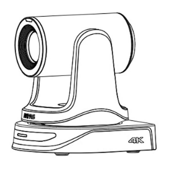
Page 9: Camera Dimension
CAMERA DIMENSION(MM) -
Page 10: Wall Mount Installation
WALL-MOUNT INSTALLATION: 1.Drill the hole on the wall referring to the wall mounting bracket hole position, hole diameter of φ6mm, position the four φ6mm plastic expansion screws in the drilled hole. 2.Use four M4*30 self-tapping screws to mount the wall-mount bracket on the wall. 3.Fix the lower cover of the bracket to the base of the camera with imperial screws(SIZE 1/4-20UNC*3/8)... -
Page 11: Ceiling Mount Installation
CEILING-MOUNT INSTALLATION: 1.Referring to the position of the cover plate holes on the bracket in the concrete ceiling, drill a hole of φ6, and position 3 plastic expansion screws of φ6 in the hole. 2.Use three M4*30 self-tapping screws to mount the bracket the upper cover plate on the ceiling. 3.Fix the lower cover of bracket to the base of the camera with imperial screws(Size 1/4-20UNC*3/8)... -
Page 12: Ir Remote Controller
IR REMOTE CONTROLLER POWER Under normal working mode, press POWER to enter standby mode; Press it again, the camera will start self-configuration, then go back to HOME position. It will go to preset position 0 if the preset is set. FREEZE (do NOT support USB output)... - Page 13 FOCUS Manually adjust focus, only valid under manual mode. ZOOM Manually adjust zoom. NAVIGATE KEY: UP/DOWN/LEFT/RIGHT Under camera normal mode, use navigate keys to pan/ tilt; After entering camera OSD, use navigate keys to select and enter submenu. OK /HOME KEY Under camera normal mode, press OK to make the camera go back to its HOME position;...
-
Page 14: Visca In (Rs232) Port
VISCA IN (RS232 PORT) V_OU V_IN VISCA IN RS485 A(+) IR OUT B(-) VISCA IN &Mini DIN Connection Camera VISCA IN Mini DIN VISCA IN & DB9 Connection Camera VISCA IN Windows DB-9 A (+) A (+) IR OUT B (-) B (-) VISCA NETWORK CONSTRUCTION:... -
Page 15: Serial Port Configuration
SERIAL PORT CONFIGURATION: Parameter Value Parameter Value Baud rate 2400/4800/9600/115200 Stop Bit 1bit Start Bit 1 bit Check Bit None Data Bit 8 bit OSD MENU 1. Under working mode, press the MENU key on the IR remote controller, to enter the OSD menu as shown bellow: 2. - Page 16 AT RATIO 1/6/,1/8,1/10,1/12,1/16,1/20, Body Default: 1/16 EXPOSURE AUTO/ MANUAL/ SHUTTER/ IRIS/ BRIGHT Default: AUTO MODE Shutter speed: 1/30~1/10000, only valid under MANUAL Default: AUTO SHUTTER and SHUTTER mode IRIS Iris setting: CLOSE~F14, only valid under MANUAL and Default: AUTO IRIS mode EXPOSURE GAIN Gain setting:0dB~30dB, only valid under MANUAL mode...
- Page 17 less motion noise on image, high value will cause image smear. SHARPNESS Sharpness setting: 0~15 Default: 6 CONTRAST Set contrast level: 0~15 Default: 8 SATURATION Set saturation level: 0~15 Default: 8 GAMMA Select gramma level: 0~15 Default: 8 IMAGE STYLE USER/NORMAL/COLORFULL Default: USER FOCUS...
- Page 18 TALLY OFF/LOW/MIDDLE/HIGH Default: LOW BRIGHT Note: After selecting the system, press OK to confirm. If it is the currently selected system, it will not be activated. DHCP ON/OFF 192.168.001.188 MASK 255.255.255.000 192.168.001.001 Use up/down/left/right navigation keys to select (Gateway) item to set, and use numeric keys to enter SETTINGS parameters.
-
Page 19: Uvc Control
SET IP ADDRESS IN MENU In order to facilitate customer debugging, the camera supports IP address configuration under OSD. 1. Press "MENU" to enter into the camera OSD, then select “IP SETTINGS”; 2. Press “” navigation key to enter the IP setting interface. Select the parameter needs to be changed using the navigation “”... -
Page 20: Web Settings
PU_BACKLIGHT_COMPENSATION_CONTROL 81 01 04 33 02/03 FF PU_POWER_LINE_FREQUENCY_CONTROL 8x 01 04 AA 00/01/02 FF CT_ZOOM_ABSOLUTE_CONTROL 8x 01 04 47 0p 0q 0r 0s FF CT_PANTILT_ABSOLUTE_CONTROL 8x 01 06 02 VV WW 0Y 0Y 0Y 0Y 0Z 0Z 0Z 0Z F CT_PANTILT_RELATIVE_CONTROL 8x 01 06 01 pp qq rr ss FF CT_ZOOM_RELATIVE_CONTROL... - Page 21 On the Preview interface shown above, there is a virtual control panel on the right-hand side. Options include pan, tilt, zoom, focus, presets, focus speed, zoom speed and tracking controls. On the bottom of image preview, main stream and sub stream preview can be selected. Configuration Click “Setting”...
- Page 22 Video Transmission: To set RTMP and SRT settings.
- Page 23 Audio Setting: To enable/disable embedded audio. Audio encoding mode can be selected. Parameters such as sampling rate, bit rate and volume can be adjusted. Image Parameter: To set focus, exposure, white balance, image, image quality, noise-reduction and video format, etc.
- Page 24 Tracking Setting: To Enable, Target position, Target scaling, Target Switching, Target Lost Timeout, PT Limitation, and blackboard area, etc. The Tracking Settings allow you to fine-tune the camera's tracking behavior for optimal performance in various scenarios • Enable: to enable tracking or not •...
- Page 25 • Target lost timeout: ranging from 2s to 10s • Target switching: switch the target • Pan/Tilt Limit: the pan, tilt limitation area can be set when you only want to track within the limitation area • Initial Position Set: when there is no tracking target in the area, the camera will go back to preset initial position •...
- Page 26 System Mode: To select the system mode for the camera. • Mode 0: when IP and HDMI are selected to output 4KP60, SDI output will be no video image • Mode 1: when IP outputs 4KP30 and HDMI outputs 4KP60, SDI can output up to 1080P60. Reset Options: To reset the camera to default settings.
- Page 27 Account Setting: To set camera account login ID and password. System Time: To set the time zone and NTP enable.
-
Page 28: Visca Over Ip
RTSP/RTMP LINK FOR STREAMING Default RTSP main streaming URL: rtsp://192.168.1.188/stream/main Default RTSP sub streaming URL: rtsp://192.168.1.188/stream/sub Default RTMP main streaming URL: rtmp://192.168.1.188:1935/app/rtmpstream0 Default RTMP sub streaming URL: rtmp://192.168.1.188:1935/app/rtmpstream1 VISCA OVER IP VISCA over IP means VISCA protocol transmit via IP. This can be used to reduce RS232/RS485 cable layout (the controller must support IP communication function). - Page 29 receives the command, it will return required message. VISCA Reply It is sent from peripheral equipment (camera) to controller. ACK, which is the complete message, can be either reply or error reply. Command format: Note that LAN output is big-endian, and LSB is in the front. Payload type: data definitions are listed below: Name Value (Byte 0)
- Page 30 ⚫ Controlled reply: The following data is saved in return command payload of control command. Delivery confirmation: VISCA over IP uses UDP as transmission communication protocol. UDP communication message transmission is not stable, it is necessary to confirm delivery and resent in application. Generally, when controller sends a command to peripheral equipment, controller will wait for the return message then send the next command, we can detect and confirm if the peripheral equipment receive the commands from its return message’s lag time.
-
Page 31: Visca Protocol
Sequence chart when command lost Sequence chart when returned message lost Note: Do not change IP address, subnet mask, or gateway parameters under VISCA over IP mode, otherwise, it will cause network inconsistency. VISCA PROTOCOL Part 1 Camera Return Commands Ack/Completion Message Command Note... - Page 32 Command Returned when a command cannot be executed due to current z0 61 41 FF conditions. For example, when commands controlling the focus Executable manually are received during auto focus. Part 2 Camera Control Commands Command type function command AddressSet Broadcast 88 30 01 FF Address setting...
- Page 33 Command type function command (Standard) Far (Variable) 81 01 04 08 2p FF p=0 (Low) to 7 (High) Near 81 01 04 08 3p FF p=0 (Low) to 7 (High) (Variable) Direct 8x 01 04 48 0p 0q 0r 0s FF pqrs: Focus Position Auto Focus 81 01 04 38 02 FF...
- Page 34 Command type function command control) Reset 8x 01 04 0A 00 FF 8x 01 04 0A 02 FF Shutter Setting CAM_Shutter Down 8x 01 04 0A 03 FF 8x 01 04 4A 00 00 0p 0q Shutter Position Direct (0~0x15) Reset 8x 01 04 0B 00 FF 8x 01 04 0B 02 FF...
- Page 35 Command type function command set) 255) 8x 01 04 3F 01 0p 0p FF Corresponds to 0 to 9 on the Recall 8x 01 04 3F 02 0p 0p FF Remote Commander 8x 01 04 61 02 FF Image Flip Horizontal CAM_LR_Reverse ON/OFF...
- Page 36 Command type function command 4:LPCM 5: ACC ij: bitrate*1000 50HZ 81 01 04 23 01 FF FLICK 60HZ 81 01 04 23 02 FF 81 01 04 23 00 FF Video format 1080P60 0x00 1080P50 0x01 1080I60 0x02 1080I50 0x03 1080P30 0x04 1080P25...
- Page 37 Command type function command 4K@29.97 0x1A pqrs: Camera ID (=0000 to CAM_ID Write 8x 01 04 22 0p 0q 0r 0s FF FFFF) DHCP off 8x 01 04 AE 00 FF DHCP off DHCP control DHCP on 8x 01 04 AE 01 FF DHCP on 8x 01 04 AB 0p 0q 0r 0s Set ip to:pq.rs.mn.xy...
- Page 38 Command type function command Menu Back 8x 01 06 06 10 FF Menu step back Menu Ok 8x 01 7E 01 02 00 01 FF Menu ok 8x 01 06 08 02 FF IR(remote commander) IR_Receive 8x 01 06 08 03 FF receive ON/OFF On/Off 8x 01 06 08 10 FF...
- Page 39 CAM_DZoom On Off 8x 09 04 06 y0 50 0p FF p: 2: ON 3: OFF 8x 09 04 C1 CAM_PT Speed Inq(IR) y0 50 pp FF pp: 0x05~0x18 y0 50 02 FF Auto Focus CAM_FocusModeInq 8x 09 04 38 FF y0 50 03 FF Manual Focus CAM_FocusPosInq...
- Page 40 y0 50 03 FF CAM_IDInq 8x 09 04 22 FF y0 50 0p 0q 0r 0s FF pqrs: Camera ID CAM_DHCPInq 8x 09 04 AE FF y0 50 pp FF y0 50 0p 0p 0q 0q 0r CAM_IPInq 8x 09 04 AB FF 0r 0s 0s FF y0 50 0p 0p 0q 0q 0r CAM_MASKInq...
-
Page 41: Pelco-D Protocol
Note: 【x】means the camera address: 【y】=【x + 8】. VISCA Pan Tilt Absolute Position Value Pan Angle VISCA Value Tilt Angle VISCA Value -170 0xF670 0xFE50 -135 0xF868 0x0000 0xFAF0 0x01B0 0xFD78 0x0360 0x0000 0x510 0x0288 0x0510 0x0798 0x0990 VISCA Pan Tilt Speed Value Pan (Degree/Second) Pan (Degree/Second)) PELCO-D PROTOCOL COMMAND LIST... -
Page 42: Pelco-P Protocol
Upleft 0xFF Address 0x00 0x0C Pan Speed Tilt Speed Upright 0xFF Address 0x00 0x0A Pan Speed Tilt Speed DownLeft 0xFF Address 0x00 0x14 Pan Speed Tilt Speed DownRight 0xFF Address 0x00 0x12 Pan Speed Tilt Speed Zoom In 0xFF Address 0x00 0x20 0x00... - Page 43 Focus 0Xa0 Address 0x00 0x80 0x00 0x00 0Xaf Focus 0Xa0 Address 0x01 0x00 0x00 0x00 0Xaf Near Stop 0Xa0 Address 0x00 0x00 Pan Speed Tilt Speed 0Xaf 0xA0 Address 0x00 0x03 0x00 Preset ID 0xAF Preset Clear 0xA0 Address 0x00 0x05 0x00 Preset ID...
-
Page 44: Warranty
This Limited Warranty covers any defect in material and workmanship under normal use within the Warranty Period. AVIPAS Inc. will repair or replace the qualified products at no charge. AVIPAS Inc. provides a two (2)-year warranty (from the date of purchase) for this HD Conference Camera.
Need help?
Do you have a question about the AV-2040 and is the answer not in the manual?
Questions and answers