
Related Manuals for Avipas AV-2020


Summary of Contents for Avipas AV-2020
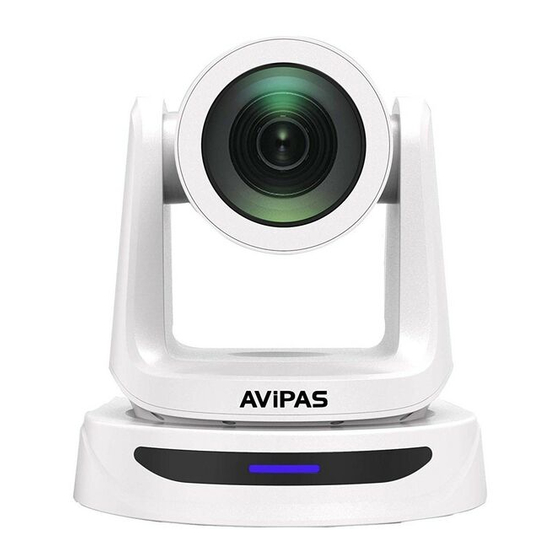
- Page 1 Model: AV-2020 20x HD All-in-one PTZ Camera User Manual V1.0 Please read this user manual thoroughly before using. www.avipas.com...
- Page 2 Preface Thank you for using this HD All-in-one PTZ Camera. This manual introduces the functions, installation process and operation of the HD camera. Prior to installation and usage, please read the manual thoroughly. Precautions This product should only be used under the specified conditions in order to avoid any damage to the camera: ◼...
-
Page 3: Table Of Contents
CONTENT SAFETY GUIDES ............................1 PACKING LIST............................. 2 QUICK START .............................. 2 PRODUCT HIGHLIGHTS..........................3 CAMERA SPECIFICATIONS ........................3 CAMERA INTERFACE..........................5 CAMERA DIMENSION..........................5 IR REMOTE CONTROLLER........................6 VISCA IN (RS232) PORT..........................9 OSD MENU..............................10 UVC CONTROL ............................ -
Page 4: Safety Guides
SAFETY GUIDES 1. Electric Safety Installation and operation must accord with electric safety standard. 2. Use caution to transport Avoid stress, vibration or soakage in transport, storage and installation. 3. Polarity of power supply The power supply of this product is +12V, the max electrical current is 2A. Polarity of the power supply plug is shown in the drawing below. -
Page 5: Packing List
PACKING LIST When unpacked, check if all supplied accessories are included: Camera ··································································· 1pc Power Adapter ··························································· 1pc Power Cable ····························································· 1pc RS232 Control Cable ··················································· 1pc USB2.0 Cable ··························································· 1pc Remote Controller ······················································ 1pc User Manual ····························································· 1pc Double-sided Adhesive················································· 1pc QC certification ·························································... -
Page 6: Product Highlights
Dial Switch (USB) Dial Switch SW-5 SW-6 Instruction SW-3 SW-4 Instruction Updating mode reserve Working mode reserve Undefined reserve Undefined reserve PRODUCT HIGHLIGHTS ▪ Adopts advanced ISP, 1/2.8-inch 5MP sensor, providing full HD video resolution. ▪ High-quality 20x optical zoom, 2x digital zoom lens with 72.5-degree field of view. ▪... - Page 7 1920*1080@1~30 / 1280*720@1~30 / 1024*576 @1~30 (Main stream) RJ45 1280*720@1~30 / 1024*576@1~30 / 640*360 @1~30 (Sub stream) Video Interface HDMI,3G-SDI, RJ45, USB2.0 Sensor 1/2.8” 5MP CMOS sensor Zoom F4.9~98mm (20X) View angle: 60°(Far)~3.23°(Near) Rotation Angle Pan: -170° ~ +170° Tilt: -90° ~ +90° Rotation Speed Pan: 0°~120°/s Tilt: 0°~80°/s...
-
Page 8: Camera Interface
CAMERA INTERFACE 1. Camera Lens 6. Tripod Screw Hole 11.3G-SDI Output 2. Camera Base 7. Installation Hole 12, USB Output 3. IR Receiver Panel 8. RS232 Control Input 13, RJ45 Output 4. Power Indicator Light 9. RS232 Control Output 14. DC12V Power Jack 5. -
Page 9: Camera Dimension
CAMERA DIMENSION(MM) -
Page 10: Ir Remote Controller
IR REMOTE CONTROLLER POWER Under normal working mode, press POWER to enter standby mode; Press it again, the camera will start self-configuration, then go back to HOME position. It will go to preset position 0 if the preset is set. FREEZE (do NOT support USB output)... - Page 11 FOCUS Manually adjust focus, only valid under manual mode. ZOOM Manually adjust zoom. NAVIGATE KEY: UP/DOWN/LEFT/RIGHT Under camera normal mode, use navigate keys to pan/ tilt; After entering camera OSD, use navigate keys to select and enter submenu. OK /HOME KEY Under camera normal mode, press OK to make the camera go back to its HOME position;...
-
Page 12: Visca In (Rs232) Port
VISCA IN (RS232 PORT) V_OU VISCA V_IN RS485 A(+) IR OUT B(-) VISCA IN & DB9 Connection Camera VISCA IN Windows DB-9 A (+) IR OUT B (-) VISCA IN &Mini DIN Connection VISCA Network Construction: Camera VISCA Mini DIN A (+) B (-) SERIAL PORT CONFIGURATION... -
Page 13: Osd Menu
OSD MENU 1. Under working mode, press the MENU key on the IR remote controller, to enter the OSD menu as shown bellow: 2. After entering the main menu, use navigate UP/DOWN keys to select the from the main menu options. 3. - Page 14 WD MODE ON/OFF Default: OFF WDR Level Default: 1 LEVEL ON/OFF Default: OFF WB MODE ATW/ MANUAL/ AUTO/ INDOOR/ OUTDOOR/ PUSH Default: ATW Red gain level: 0~255, only valid under manual white R GAIN Default: AUTO balance mode. B GAIN Blue gain level:0~255, only valid under manual white Default: AUTO balance mode...
- Page 15 MENU MIR NORMAL/ MIRROR Default: NORMAL 1080P59.94 1080P50 1080I59.94 1080I50 1080P29.97 1080P25 720P59.94 After selecting the system, press OK to confirm. If it is the currently selected 720P50 system, it will not be activated. 720P29.97 720P25 1080P60 FORMAT 1080P30 720P60 720P30 1080I60 1080P24...
-
Page 16: Uvc Control
ALL RESET Reset all settings to default IR ADDR Camera IR control address USB firmware version CLIENT Default client end protocol: VISCA MODEL NO. Model number INFO ARM VER ARM firmware version FPGA VER FPGA firmware version CAM VER Camera version RELEASE Software release date SET IP ADDRESS IN MENU... -
Page 17: Web Settings
2. The interval of control commands sending from the server (via USB) to the camera should be no less than 250ms. PU_BRIGHTNESS_CONTROL 81 01 04 4d 00 00 0p 0q FF PU_CONTRAST_CONTROL 81 01 04 A2 00 00 0p 0q FF PU_SATURATION_CONTROL 81 01 04 A1 00 00 0p 0q FF PU_SHARPNESS_CONTROL... - Page 18 On the Preview interface shown above, there is a virtual control panel on the right-hand side. Options include pan, tilt, zoom, focus, presets, focus speed and zoom speed. On the bottom of image preview, main stream and sub stream preview can be selected. Configuration Click “Setting”...
- Page 19 Video Transmission: To set RTMP settings. Audio Setting: To enable/disable embedded audio. Audio encoding mode can be selected. Parameters such as sampling rate and bit rate can be adjusted. Image Parameter: To set focus, exposure, white balance, image, image quality, noise-reduction, etc.
- Page 20 Ethernet: To set DHCP mode, IP address, subnet mask, default gateway, http port, web port, main stream port and sub stream port. Default settings are as following: DHCP Default gateway 192.168.1.1 IP address 192.168.1.188 HTTP port Subnet mask 255.255.255.0 RTSP port Firmware upgrade: To update the camera ISP.
-
Page 21: View Rtsp Stream Via Vlc
Reset to default: To reset the camera to default settings. Reset simply: reset camera image settings; Reset completely: reset all camera settings including IP configurations, image settings, language and protocol; Reboot: reboot ISP part of the camera. Account Setting: To set camera account username and password. USING VLC TO VIEW RTSP/RTMP VIDEO Default RTSP main streaming URL: rtsp://192.168.1.188/stream/main Default RTSP sub streaming URL: rtsp://192.168.1.188/stream/sub... -
Page 22: Visca Over Ip
VISCA OVER IP VISCA over IP means VISCA protocol transmit via IP. This can be used to reduce RS232/RS485 cable layout (the controller must support IP communication function). Communication port specs: ⚫ Control port: RJ45 Gigabit LAN ⚫ IP protocol: IPv4 ⚫... - Page 23 Payload type: data definitions are listed below: Name Value (Byte 0) Value (Byte 0) Value (Byte 0) VISCA command 0x01 0x00 Stores the VISCA command. VISCA inquiry 0x01 0x10 Stores the VISCA inquiry. Stores the reply for the VISCA command and VISCA reply 0x01 0x11...
- Page 24 ⚫ Controlled reply: The following data is saved in return command payload of control command. Delivery confirmation: VISCA over IP uses UDP as transmission communication protocol. UDP communication message transmission is not stable, it is necessary to confirm delivery and resent in application. Generally, when controller sends a command to peripheral equipment, controller will wait for the return message then send the next command, we can detect and confirm if the peripheral equipment receive the commands from its return message’s lag time.
-
Page 25: Visca Protocol
Sequence chart when command lost Sequence chart when returned message lost Note: Do not change IP address, subnet mask, or gateway parameters under VISCA over IP mode, otherwise, it will cause network inconsistency. VISCA PROTOCOL Part1 Camera Return Commands Ack/Completion Message Command Note Packet... - Page 26 Command type function command IF_Clear Broadcast 88 01 00 01 FF I/F Clear CommandCancel 8x 21 FF 8x 01 04 00 02 FF CAM_Power Power ON/OFF 8x 01 04 00 03 FF Stop 8x 01 04 07 00 FF Tele (Standard) 8x 01 04 07 02 FF Wide (Standard) 8x 01 04 07 03 FF...
- Page 27 Command type function command OnePush 8x 01 04 35 03 FF 8x 01 04 35 04 FF Manual 8x 01 04 35 05 FF Sodium lamp 8x 01 04 35 08 FF fluorescent 8x 01 04 35 09 FF OnePush Trigger 8x 01 04 10 05 FF Reset 8x 01 04 03 00 FF...
- Page 28 Command type function command 8x 01 04 0D 02 FF Down 8x 01 04 0D 03 FF Direct 8x 01 04 4D 00 00 0p 0q FF pq: Bright l Positon (0~0x1B) pq: Bright l Positon (0~0x0F) CAM_OverallBright Direct 8x 01 04 A4 00 00 0p 0q FF different with AE BRIGHT 8x 01 04 3D 02 FF Exposure...
- Page 29 Command type function command Down 8x 01 04 A4 03 FF Mount Down CAM_ColorGain Direct 8x 01 04 49 00 00 00 0p FF (0~0x0E) 0 – OFF CAM_2D Direct 8x 01 04 53 0p FF 1 – ON Noise Reduction 0 –...
- Page 30 Command type function command DownLeft 8x 01 06 01 VV WW 01 02 FF DownRight 8x 01 06 01 VV WW 02 02 FF Stop 8x 01 06 01 VV WW 03 03 FF 8x 01 06 02 VV WW AbsolutePosition 0Y 0Y 0Y 0Y 0Z 0Z 0Z 0Z FF 8x 01 06 03 VV WW...
- Page 31 y0 50 03 FF CAM_LR_ReverseInq 8x 09 04 61 FF y0 50 02 FF y0 50 03 FF CAM_PictureFlipInq 8x 09 04 66 FF y0 50 02 FF y0 50 03 FF CAM_IDInq 8x 09 04 22 FF y0 50 0p 0q 0r 0s FF pqrs: Camera ID 8x 09 04 AE CAM_DHCPInq...
-
Page 32: Pelco-D Protocol
8x 09 04 C3 01 y0 50 0p 0q 0r 0s 0m 0n SubstreamRateInq pqrsmnxy: bitrate (0~15360) 0x 0y FF Note: 【x】 means the camera address: 【y】=【x + 8】. VISCA Pan Tilt Absolute Position Value Pan Angle VISCA Value Tilt Angle VISCA Value -170 0xF670... -
Page 33: Pelco-P Protocol
Left 0xFF Address 0x00 0x04 Pan Speed Tilt Speed Right 0xFF Address 0x00 0x02 Pan Speed Tilt Speed Upleft 0xFF Address 0x00 0x0C Pan Speed Tilt Speed Upright 0xFF Address 0x00 0x0A Pan Speed Tilt Speed DownLeft 0xFF Address 0x00 0x14 Pan Speed Tilt Speed... - Page 34 DownRi 0Xa0 Address 0x00 0x12 Pan Speed Tilt Speed 0Xaf Zoom In 0Xa0 Address 0x00 0x20 0x00 0x00 0Xaf Zoom 0Xa0 Address 0x00 0x40 0x00 0x00 0Xaf Focus 0Xa0 Address 0x00 0x80 0x00 0x00 0Xaf Focus 0Xa0 Address 0x01 0x00 0x00 0x00 0Xaf...
-
Page 35: Warranty
This Limited Warranty covers any defect in material and workmanship under normal use within the Warranty Period. AVIPAS Inc. will repair or replace the qualified products at no charge. AVIPAS Inc. provides a two (2)-year warranty (from the date of purchase) for this HD Conference Camera.
Need help?
Do you have a question about the AV-2020 and is the answer not in the manual?
Questions and answers