SOLIS RHI Series Instruction Manual
Hybrid inverter
Hide thumbs
Also See for RHI Series:
- Instruction manual (25 pages) ,
- Instruction manual (34 pages) ,
- Instruction manual (27 pages)
Table of Contents
Advertisement
Quick Links
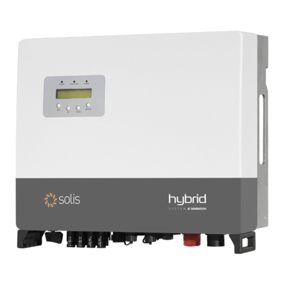
Solis RHI Series Hybrid Inverter
Instruction Manual
(RHI-3P(3-10)K-HVES-5G)
Ver 1.7
Ginlong Technologies Co., Ltd.
No. 57 Jintong Road, Binhai Industrial Park, Xiangshan, Ningbo,
Zhejiang, 315712, P.R.China.
Tel: +86 (0)574 6578 1806
Fax: +86 (0)574 6578 1606
Please adhere to the actual products in case of any discrepancies in this user manual.
If you encounter any problem on the inverter, please find out the inverter S/N
and contact us, we will try to respond to your question ASAP.
Ginlong Technologies Co., Ltd.
Advertisement
Table of Contents

Subscribe to Our Youtube Channel
Related Manuals for SOLIS RHI Series


Summary of Contents for SOLIS RHI Series
- Page 1 Solis RHI Series Hybrid Inverter Instruction Manual (RHI-3P(3-10)K-HVES-5G) Ver 1.7 Ginlong Technologies Co., Ltd. No. 57 Jintong Road, Binhai Industrial Park, Xiangshan, Ningbo, Zhejiang, 315712, P.R.China. Tel: +86 (0)574 6578 1806 Fax: +86 (0)574 6578 1606 Please adhere to the actual products in case of any discrepancies in this user manual.
-
Page 2: Table Of Contents
Contents 1. Introduction 1.1 Product Description 1.2 Packaging 2. Safety & Warning 2.1 Safety 2.2 General Safety Instructions 2.3 Notice For Use 3. Overview 3.1 Screen 3.2 Keypad 3.3 Terminal Connection 4. Installation 4.1 Select a Location for the Inverter 4.2 Mounting the Inverter 4.3 PV Input Terminal Assembly 4.4 Battery Terminal Components... -
Page 3: Introduction
1.2 Packaging 1.1 Product Description The Solis RHI series is designed for residential hybrid systems, which can work with Please ensure that the following items are included in the packaging with your machine: batteries to optimize self-consumption. The unit can operate in both off- and on-grid modes. -
Page 4: Safety & Warning
NEC Article 690, Part II. All Solis single phase inverters feature an integrated WARNING: DC switch. “Warning” indicates a hazardous situation which if not avoided, could result CAUTION: in death or serious injury. -
Page 5: Notice For Use
× 3 Phase LOAD Figure 3.2 Keypad 3.3 Terminal Connection Solis RHI series inverter is different from normal on-grid inverter, please refer to the instructions below before start connection. WARNING: Please refer to the specification of the battery before configuration. -
Page 6: Installation
4. Installation 4. Installation 4.1 Select a Location for the Inverter Install on a wall or strong structure capable of bearing the weight of the machine (24kg). To select a location for the inverter, the following criteria should be considered: Install vertically with a maximum incline of +/- 5 degrees, exceeding this may cause Exposure to direct sunlight may cause output power derating. -
Page 7: Mounting The Inverter
Make sure the DC-switch, battery, AC-BACKUP, and AC-Grid are all in their off-states. Make sure the PV resistance to ground is higher than 20K ohms. The Solis RHI series inverter uses the MC4 connectors. Please follow the picture below to assemble the MC4 connectors. -
Page 8: Battery Terminal Components
4. Installation 4. Installation 4.4 Battery Terminal Components 4.5 Assembling the AC Connector Quick connector is used for battery connection. The connector is suitable for tin-plated cables There are two AC terminals and the assembly steps for both are the same. with a conductor cross section of 2.5-6mm2 (AWG14-10). -
Page 9: Meter Installation
4.6 Meter Installation A) Stripped the insulation sleeve of cable for 70mm, so that bared copper-cored connector Solis RHI-(3-10)K-HVES-5G series inverter integrated export power control function, this function reaches for 13mm. Cable through nut and sleeve of socket element, insert corresponding need connect a 3-Phase power meter for export power controlling. -
Page 10: Communication Cable Assembly
4. Installation 4.7 Communication C able Assembly The RHI series inverter uses RS485 cable to communicate with the Meter and CAN to Procedure for connecting the RS485 cable: communicate with the battery's BMS. The image below shows the assembly of the RS485/CAN 1. -
Page 11: Led Indicates
2. Use the network wire stripper to strip the insulation layer of the communication cable. The inverter can be monitored via Wi-Fi or GPRS. All Solis communication devices are According to the standard line sequence of figure 4.22 connect the wire to the plug of optional. -
Page 12: Operation
5. Operation 5. Operation 5.2 Information In the information section, operating data and information data can be viewed. Sub-sections include: Pressing the ESC main menu 1.General Info key calls back the previous menu 2.System Info Information 3.Energy Records UP/DOWN 4.PVEnergy Records 5.BMS Info Settings 6.Meter Info... - Page 13 5. Operation 5. Operation Display Description Display Description Duration Duration V_DC1: Shows input 01 voltage value. V_DC1: 000.0V BattChgE Total: 10 sec 10 sec Shows the total battery charged energy. I_DC1: 000.0A I_DC1: Shows input 01 current value. 0000000kWh V_DC2: Shows input 02 voltage value. V_DC2: 000.0V BattChgE Today:...
-
Page 14: Settings
5. Operation 5. Operation 5.3 Settings The following submenus are displayed when the Settings menu is selected: Display Description Duration 1. Set Time/Date 2. Set Address Battery V: Shows battery voltage(From BMS). Battery V: 000.0V 10 sec Battery I: +00.0A Battery I: Shows battery current(From BMS). -
Page 15: Advanced Information
T: 00-00 00:00 D:0000 Grid Standard: Shows current effective grid standard. 10 sec Figure 5.11 Alarm Message Flash State: 10 sec Reserved for Solis Technicians 00000000 Figure 5.14 General Status NOTE: The advanced status is reserved for Solis technicians. .26. .27. -
Page 16: Advanced Settings
Press the ESC key to cancel changes and returns to previous menu. NOTE For different countries, the grid standard needs to be set as different according to local requirements. If there is any doubt, please consult Solis service technicians for details. .28. .29. - Page 17 5. Operation 5. Operation 5.5.2 Grid Switches This function is used to start or stop the generation of the inverter. Overdischg SOC: 020% Grid ON Grid OFF Figure 5.22 Overdischg SOC Figure 5.19 Set Grid ON/OFF 5.5.4 Backup Control Screens can be scrolled manually by pressing the UP/DOWN keys. This section is used to set the configuration of the backup port.
-
Page 18: Meter Select
5. Operation 5. Operation 5.5.5.1 Meter Select The setting is used to select the meter type based on the actual configuration. Mode 2: Feed In Priority Mode Logic(Feed the excess PV to Grid in order to gain subsidies) PV Power Using Priority: Load>Grid>Battery Meter Type: Load Support Priority: PV>Battery>Grid 3Ph Meter... - Page 19 5. Operation 5. Operation 5.5.8 Export power Set Mode 4: Off Grid Mode Logic(For Off-grid use and AC-Grid Port Disconnected) This function is to set the export power control. OverDischg SOC for Off-Grid Setting Range: From Battery “Forcecharge SOC” to 100% 1.EPM ON/OFF PV Power Using Priority: Load>Battery 2.
-
Page 20: Afci Function
5. Operation 5. Operation 5.5.10 Restart HMI 5.6 AFCI function This function is to reboot the LCD screen. Inverters have the built-in AFCI function which can detect the arc fault on the DC circuit and shut down the inverter to prevent a fire disaster. 5.5.11 Self Test CEI 0-21 5.6.1 Enable the AFCI function This function is only available when Italian standard CEI021 is selected. -
Page 21: Commissioning
6.1 Preparation of Commissioning Ensure all the devices are accessible for operation, maintenance and service. Solis RHI Series inverter does not require any regular maintenance. However, cleaning the Check and confirm that the inverter is firmly installed. heatsink will help inverter dissipating heat and increase the lifetime of inverter. The dirt on the Space for ventilation is sufficient for one inverter or multiple inverters. - Page 22 7. Troubleshooting 7. Troubleshooting When faults occur, the “Fault” state will be shown on the main screen. Alarm Message Failure description Solution Follow the steps below to check what fault occurs. 1. Check if there’s arc in PV connection ARC-FAULT ARC detected in DC circuit Steps: Enter →...
- Page 23 OV-ILLC LLC hardware overcurrent 2. Return-factory repair 1. Serial number of Solis Single Phase Inverter; 2. The distributor/dealer of Solis Single Phase Inverter (if available); Bypass overvoltage fault OV-VBackup 3. Installation date. 4. The description of problem (i.e. the alarm message displayed on the LCD and the status 1.
-
Page 24: Specifications
8. Specifications 8. Specifications Technical Data RHI-3P3K-HVES-5G* RHI-3P4K-HVES-5G* Technical Data RHI-3P3K-HVES-5G* RHI-3P4K-HVES-5G* Input DC (PV side) Output AC(Back-up) Recommended max. PV power Rated output power 4800W 6400W Max. input voltage Peak apparent output power 1000V 10000VA, 60 sec 10000VA, 60 sec Rated voltage 600V Back-up switch time... - Page 25 8. Specifications 8. Specifications Technical Data RHI-3P3K-HVES-5G* RHI-3P4K-HVES-5G* Technical Data RHI-3P5K-HVES-5G RHI-3P6K-HVES-5G Input DC (PV side) General data Dimensions(W/H/D) Recommended max. PV power 535*455*181mm 8000W 9600W Weight 25.1kg Max. input voltage 1000V Topology Transformerless Rated voltage 600V Self consumption (Night) <7 W Start-up voltage 160V...
- Page 26 8. Specifications 8. Specifications Technical Data RHI-3P5K-HVES-5G RHI-3P6K-HVES-5G Technical Data RHI-3P5K-HVES-5G RHI-3P6K-HVES-5G Output AC(Back-up) General data Rated output power Dimensions(W/H/D) 535*455*181mm Peak apparent output power Weight 25.1kg 10000VA, 60 sec 12000VA, 60 sec Back-up switch time < 40ms Topology Transformerless Rated output voltage Self consumption (Night) <7 W...
- Page 27 8. Specifications 8. Specifications Technical Data RHI-3P8K-HVES-5G RHI-3P10K-HVES-5G Technical Data RHI-3P8K-HVES-5G RHI-3P10K-HVES-5G Input DC (PV side) Output AC(Back-up) Recommended max. PV power Rated output power 12800W 16000W 10kW Max. input voltage Peak apparent output power 1000V 16000VA, 60 sec Rated voltage 600V Back-up switch time <...
-
Page 28: Appendix
It is for your reference only. If customer has any doubts or uncertainty, please Noise emission <30 dB (A) consult Solis service department for confirmation. Cooling concept Natural convection To set the correct grid code, please enter the following path: Max.operation altitude... - Page 29 9. Appendix Code in LCD Country/Region Comments G98 NI North Ireland For North Ireland Low Voltage Grid <16A G99 NI North Ireland For North Ireland Low Voltage Grid >16A User-define Customized Protection Limits Gen50 Generator Connected, Frequency-Derating, 50Hz Gen 60 Generator Connected, Frequency-Derating, 60Hz East Denmark For East Danish low voltage grid...
Need help?
Do you have a question about the RHI Series and is the answer not in the manual?
Questions and answers