Table of Contents
Advertisement
Ginlong Technologies Co., Ltd.
No. 57 Jintong Road, Binhai Industrial Park, Xiangshan, Ningbo,
Zhejiang, 315712, P.R.China.
Tel: +86 (0)574 65781806
Fax: +86 (0)574 65781 6 06
Email:info@ginlong.com
Web:www.ginlong.com
Please adhere to the actual products in case of any discrepancies in this user manual.
If you encounter any problem on the inverter, please find out the inverter S/N
and contact us, we will try to respond to your question ASAP.
Osoli s
Solis RHl-5G Series Hybrid Inverter
Ginlon g Technolo g ies Co., Ltd.
Instruction Manual
Ver 1.5
Advertisement
Table of Contents

Subscribe to Our Youtube Channel
Related Manuals for SOLIS RHI-5G Series


Summary of Contents for SOLIS RHI-5G Series
- Page 1 Osoli s Solis RHl-5G Series Hybrid Inverter Instruction Manual Ver 1.5 Ginlong Technologies Co., Ltd. No. 57 Jintong Road, Binhai Industrial Park, Xiangshan, Ningbo, Zhejiang, 315712, P.R.China. Tel: +86 (0)574 65781806 Fax: +86 (0)574 65781 6 06 Email:info@ginlong.com Web:www.ginlong.com Please adhere to the actual products in case of any discrepancies in this user manual.
-
Page 2: Table Of Contents
Contents ································································································································· 2 1. I n t r o du cti o n ························································································································ 1.1 Product Description •········································································································································· 1 .2 Packaging ····················································································································· 4 2 . S af e t y & W a rn i ng ..............................2.1 Safety •········································································································ 2.2 General Safety Instructions 2. -
Page 3: Product Description
1.1 Product Description 1.2 Packaging The Solis RH l-5G Series is designed for residential hybrid systems, which can work with Please ensure that the following items are included in the packaging with your machine: batteries to optimize self-consumption. The unit can operate in both off- and on-grid modes. -
Page 4: Safety & Warning
The DC OCPD shall be installed per local requirements. All photovoltaic source death or serious injury. and output circuit conductors shall have isolators that comply with the NEC Article 690, Part 1 1. All Solis single phase inverters feature an integrated WARNING: DC switch. -
Page 5: Notice For Use
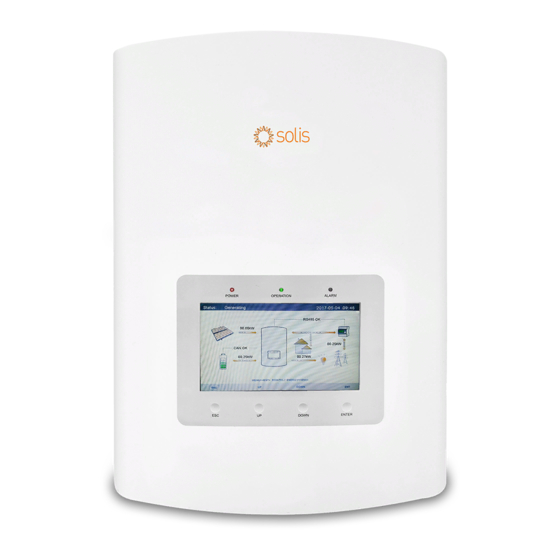
2. Safety & Warning 3. Overview 3.1 Screen Solis RHl-5G Series adopts 7 inch color screen, it displays the status, operating information and WARNING: settings of the inverter. The RHl-5G Series does not support parallel (three- and single-phase) 3.2 Keypad operation on the AC-BACKUP port. -
Page 6: Installation
4. Installation 4. Installation 4.1 Select a Location for the Inverter • Install on a wall or strong structure capable of bearing the weight of the machine (17kg). To select a location for the inverter, the following criteria should be considered: •... -
Page 7: Mounting The Inverter
4. Installation 4. Installation 4.2 Mounting the Inverter Dimensions of mounting bracket: WARNING: The inverter must be mounted vertically. 2.Lift up the inverter (be careful to avoid body strain), and align the back bracket on the inverter with the convex section of the mounting bracket. Hang the inverter on the mounting bracket and make sure the inverter is secure (see Figure 4.5) Figure 4.3 Inverter wall mounting Once a suitable location has be found accordingly to 4.1 using figure 4.3 and figure 4.4... -
Page 8: Pv Input Terminal Assembly
• Make sure the PV resistance to ground is higher than 20 K ohms. connectors. When pull out the power cable, you T he Solis RH l - 5 G Series inverter uses the MC4 connectors. must press the button as indicated in the right figure. -
Page 9: Assembling The Ac Connector
4. Installation 4. Installation 4.5 Assembling the AC Connector 4. Each of the terminals are labeled. Ensure that the correct conductor is fastened There are two AC terminals and the assembly steps for both are the same. (1.2 N.m. torque) to the correct terminal. Take out the AC connector parts from the packaging. -
Page 10: Meter Installation
4. Installation 4. Installation 4.6 Meter Installation Solis-RHl-(3-6)K-48ES-5G series inverter is able to connected Acrel meters or Eastron meters to fuilfill the control logic of the self-consumption mode, export power control, monitoring, etc. __,__._ Acre I 1 ph meter (With CT): ACR 1 0 R-D 16TE... -
Page 11: Communication Cable Assembly
4. Installation 4. Installation 4. 7 Communication Cable Assembly The RHl-5G Series inverter uses RS485 cable to communicate with the Meter and CAN to NOT E : communicate with the battery's BMS. The image below shows the assembly of the RS485/CAN For CAN cable pin 4 (blue) and pin 5 (white-blue) are used for the communication cables. -
Page 12: Logic Interface Connection
4.1 0 Inverter monitoring connection Logic interface is required by some local regulations that can be operated by a simple switch The inverter can be monitored via Wi-Fi or GPRS. All Solis communication devices are or contactor(Not available in South Africa). -
Page 13: L Ed Indicates
4. Installation 5. Operation 4.1 1 LE D Indicates There are three LED indicators on the RH I i nverter (Red , Green, and Orange) which indicate the worki ng status of the i nverter. • • Pressing the ESC m ain menu key calls back the pre vious menu... -
Page 14: Main Menu
5. Operation 5. Operation 5.2 Main Menu After setting the language, press "ESC" to access the main page. There are four submenu in the Main Menu: ■ 1 . I n formation Status: Generating 201 7-05-04 09:48 2. Sett i n g s 3 . - Page 15 Information for " PV Inverter Meter" is only available when two Eastron meters are used and Meter Placement is selected as "Grid+PV Meter". 3 / 4 Details please consult Solis service department. Figure 5. 7 Information Page 3 .26. .27.
-
Page 16: Settings
Set the time and date on the inverter. Must set this according to local time as it Set system language. Chinese and English are available. affects the daily yield calculation. (If Solis monitoring system is used, must set the correct time zone of the system, otherwise datalogger will update the inverter... -
Page 17: Advanced Info
5. Operation 5. Operation 5 . 5 . 2 R u n n i n g M essage 5.5 Advanced Information Detailed information can be viewed in this section: This function is for maintenance person to get running message such as internal temperature, 1 . - Page 18 5. Operation 5. Operation 5 . 5 . 4 C o m m u n i cati o n Data 5 . 5 . 6 M o n t h l y E n e rg y Internal communication data can b e viewed i n this section. For maintenance person only. The screen shows the inverter monthly energy detail of different month.
-
Page 19: Advanced Settings - Technicians Only
5. Operation 5. Operation 5 . 5 . 8 Tota l Ene rgy 5.6 Advanced Settings - Technicians Only The screen shows the inverter total energy detail. NOTE: Total Energy 201 5-02-23 1 9 35 This function is for authorised technicians only. Improper access and operation may result in abnormal results and damage to the inverter. - Page 20 5. Operation 5. Operation 5 . 6 . 3 Ca l i b rate 5 . 6 . 1 S e l ect Sta n d a rd This function is used to select corresponding grid standards. Warranty or maintenance may result in resetting total generating data, this function allow Please refer to the actual LCD setting for the grid standard options.
- Page 21 5. Operation 5. Operation 5 .6 . 5 Resta rt H M I T his function is to reboot the LCD sc reen. Powe r Pa ramete r Powe r Pa ra : 1.00 5 .6 .6 Stora g e E n e rg y Set T his section contains wo rking mode setting , batte ry cont rol setting , etc.
- Page 22 5. Operation 5. Operation 5 . 6 . 6 . 2 Batte ry S e l e ct This product is compatible with the following battery modules: 2 0 1 5-02-23 1 9 35 Battery Select Brand Model Setting Battery Module: Box Pro 2.
- Page 23 Due to the inconformity between battery cells, damages will be less likely to be 1. Battery Capacity: Define the capacity of the battery. avoided. Solis is not responsible for any potential damages caused by the use 2. Equalizing Voltage: Define the voltage for equalizing charge.
- Page 24 5. Operation 5. Operation 5 . 6 . 6 . 3 M eter Set 5 . 6 . 6 . 3 . 2 M eter P l ace m e n t These settings are used t o select the meter types and meter installed locations based Grid: Meter is installed at the grid connection point.
- Page 25 5. Operation 5. Operation 5 . 6 . 6 .5 Batte ry Wa ke u p 5 . 6 . 7 . 1 B a c kflow Power T his function should be activated only after the installation. In the case of a low battery Determine the allowed backfeed power.
- Page 26 5. Operation 5. Operation 5 .6 . 7 .3 F a i l Safe O N /O F F 5 .6 .9 D S P U pd ate When this Failsafe function is ON, the inverter will shutdown once it loses This function is used to update DSP software.
-
Page 27: Afci Function
5. Operation 5. Operation 5. 7 A F C I function Inverters have the built-in A FC I function which can detect the arc fault on the DC circuit WARN I N G : and shut down the inverter to prevent a fire disaster. The setting corresponds to the current status as well which can be used to 5 . -
Page 28: Maintenance
6.1 Preparation of Commissioning • Ensure all the devices are accessible for operation, maintenance and service. Solis RHl-5G Series inverter does not require any regul ar maintenance. H owever , cleaning the • Check and confirm that the inverter is firmly installed. -
Page 29: T R O U B L E S H Oo Ti
8. Troubleshooting 8. Troubleshooting Step 3 : Press D O W N to select Alarm Message , then press E N T E R. The inverter has been designed in accordance with international grid tied standards for safety , and electromagnetic compatibility requirements. Before delivering to the customer Adcanced Information 201 5-02-23 1 9 35 the inverter has been subjected to several test to ensure its optimal operation and reliability. - Page 30 8. Troubleshooting 8. Troubleshooting A l a rm Message F a i l u re description S o l u t i o n A l a rm Message F a i l u re description S o l u t i o n 1 .
-
Page 31: Specifications
1. Serial number of Solis Single Phase Inverter; Back-up switch time < 2 0 m s 2. The distributor/dealer of Solis Single Phase Inverter (if available); Rated output v oltage 1 /N/P E , 220 V/2 30 V 3. Installation date. - Page 32 9. Specifications 9. Specifications O utput AC(Gri d s i de) Genera l d ata Rated output power Dimensions(W/H/D) 3 . 6 kW 333*505*24 9 m m M a x . apparent output power Weigh t 1 7 kg 3 . 3 kVA 4kVA O peration phase 1 /N/PE...
- Page 33 9. Specifications 9. Specifications O utput AC(Gri d s i de) Tech nical Data RHl-4.6K-48 E S-5G RHl-5K-48 E S-5G I n p ut DC (PV s i de) Rated output powe r 4 . 6 kW 5 kW Recom mended max. PV powe r Max.
- Page 34 9. Specifications 9. Specifications Genera l d ata Technical Data RHl-6K-48ES-5G* I n p ut D C (PV s i de) Dimensions(W/H/D) 333*505*24 9 m m Weight 1 7 kg Recom mended max. PV powe r 8000W Topology High fre q uency insolation ( for batte ry) Max.
- Page 35 9. Specifications 9. Specifications O utput AC(Gri d s i de) Genera l d ata Rated output power Dimensions(W/H/D) 6 kW 333*505*24 9 m m M a x . apparent output power Weigh t 1 7 kg 6 kVA O peration phase 1 /N/PE Topology High freq uency insolation ( for bat tery)
-
Page 36: A Pp End I X
1 0 . A p p e n d i x 1 0.1 Battery Terminal Assembly In order to avoid DC arc, Solis suggest to install a DC switch between the battery and RHI inverter. Step 1: Wire cutting and stripping (Apply for 10mm &... - Page 37 1 0 . A p p e n d i x 1 0 . A p p e n d i x Step 3: Put the barrel and the cable conductor into the lug Cable range Crimping heigth Cable pullout force Cable size 16 mm 8.10 ±...
- Page 38 Y E S = < E N T > N O = < E S C > Therefore, a separate NPS box and firmware upgrade is needed to achieve this function. Please consult Solis technicians for details and refer to the NPS box installation manual .7 3 .
- Page 39 1 0 . A p p e n d i x 1 0 . A p p e n d i x Mode 2: Feed In P riority Mode Log i c ( Feed the excess PV to Grid i n order to g a i n s Mode 3: Backu p Mode Log i c ( Keep the Battery at a certa i n S O C a n d only use it u b s i d ies) d u ri n g power outage)
- Page 40 Path : Advanced Settings - > Storage Energy Set - > Storage Mode Select - > Off-Grid Mode - > T his mode must work with the Solis N P S switching Box. O N - > Off Grid Mode Otherwise it may cause some unexpected control mistakes.
- Page 41 It is for your reference only. If customer has any doubts or uncertainty , please RD1699 Spain For Spanish low voltage grid consult Solis service department for confirmation. General E N 50549 Requirement. To set the correct grid code, please enter the following path : Possible to be used in Cyprus , Finland, E N50549 L Advanced Settings ->...
Need help?
Do you have a question about the RHI-5G Series and is the answer not in the manual?
Questions and answers