
Subscribe to Our Youtube Channel
Related Manuals for Clenergy PV-ezRack Ascent 1.1


Summary of Contents for Clenergy PV-ezRack Ascent 1.1
- Page 1 Ascent 1.1 Code-Compliant Planning and Installation Guide Complying with Eurocodes 0-9 and VDI 6012 Last Updated - Apr. 2024...
- Page 2 Installation Guide / Ascent 1.1 Introduction The installer is solely responsible for: The Clenergy PVezRack® Ascent 1.1 is a low ballast, south/north, east-west facing solution without rails for • Complying with all applicable local or national PV installation on flat roofs. With the special design and building codes, including any that may supersede this a tilt angle of 10°...
- Page 3 Installation Guide / Ascent 1.1 Application Roof pitch: maximum 5º. Maximum solar panel dimensions: length 2350mm, width 1134mm, height 28-40mm. Array set up: maximum length 23m, maximum width 20m, please also keep at lease 20mm gap between arrays. Design Standards: •...
-
Page 4: Tools And Components
Installation Guide / Ascent 1.1 Tools and Components Tools Screw Driver Drive Bit Torque Spanner Tape String & Marker Pen Components FL-ACV11/G/10 RL-ACV11/G/10 RL-ACV11/G/15 SEB-ACV11/120 CB-ACV11/EW/250 FL-ACV11/G/15 Rear Leg 10° Start and End Base L120 Connection Base Rear Leg 15° Front Leg 10°/15°... -
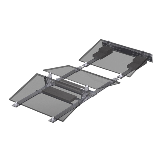
Page 5: System Overview
Installation Guide / Ascent 1.1 System Overview Overview of PVezRack Ascent 1.1 short side clamping (take 10° as an example) - North/South Facing ① ② ③ ④ ⑤ Start and End Base L120 Front Leg 10° Main Base, north/south Rear Leg 10° Wind Deflector ⑥... - Page 6 Installation Guide / Ascent 1.1 - East-west Facing ① ② ③ ④ ⑤ Start and End Base L120 Front Leg 10° Main Base, East-westh Ballast Bar Rear Leg 10° ⑥ ⑦ Connection Base Protection Mat - System Overview - Code-Compliant Planning and Installation Guide V 1.0...
-
Page 7: Installation Instruction
Installation Guide / Ascent 1.1 Installation Instruction Take East-west facing solution as an example. Base Installation Mark system start point of the Base and lay out the Start and End Base, Front Leg, Main Base according to the planning documents. Please lay out all components from East to West direction. - Page 8 Installation Guide / Ascent 1.1 Protection Mat Installation Install Protection Mat under Base where Front Leg and Rear Leg are installed. Protection Mat under Front Leg P re ss t h e B a s e d ow n to s e c u re l y f i t i nto Protection Mat shown in the right figures.
- Page 9 Installation Guide / Ascent 1.1 Protection Mat under Rear Leg Press the Base down to securely fit into Protection Mat. Slide Protection Mat to fit into the hole in the base until you hear a clicking sound. Notes: Normally the Protection Mat should be installed into hole 1.
- Page 10 Installation Guide / Ascent 1.1 Mounting hole 1 For Panel width: 1018-1052mm Mounting hole 2 For Panel width: 1052-1086mm Mounting hole 3 For Panel width: 1086-1120mm Mounting hole 4 For Panel width: 1120-1155mm Mounting hole 5 For Panel width: 1155-1190mm Click! Ballast Placement There are two different ways to place ballast blocks.
- Page 11 Installation Guide / Ascent 1.1 Opinion 2: On Ballast Bar Place the ballast blocks centrally on Ballast Bar and fasten with 4 sets of T-head bolt and nut with a torque of 10 N.m. PV Module Installation Put the module on the Front Leg and Rear Leg. Leave an approx.
- Page 12 Installation Guide / Ascent 1.1 Grounding Lug Installation It is required to install one Grounding Lug per row of base. The recommended torque of the bolt M6*14 is 4 N•m. Fix the Grounding lug on the end of base. Make sure the inner face of side opening of Grounding lug is closely attach to the base as shown in right figure.
- Page 13 Clenergy Deutschland Gmbh Willy-Brandt-Straße 23, Phone: +49 (0) 40 3562 389 00 20457 Hamburg, Germany Email: sales@clenergy.com Web: www.clenergy.com @ClenergyGlobal / @ClenergyClub / @ClenergyAUS / @ClenergyThailand @Clenergy_global @Clenergy @Clenergy @ClenergyClub A Clenergy Technologies Company...
Need help?
Do you have a question about the PV-ezRack Ascent 1.1 and is the answer not in the manual?
Questions and answers