Table of Contents
Advertisement
Installation Manual with Service Replacement Parts
CGM7-1
clockwise rotation
(access door right)
P.O. Box 4149
Winston-Salem, NC 27115
336/661-1556 Fax: 336/661-1660
Toll-free: 800.858.4477
CGM7
clockwise rotation
(access door front)
CGM7-2
counter-clockwise rotation
(access door left)
2674 N. Service Road, Jordan Station
Ontario, Canada L0R 1S0
905/562-4195 Fax: 905/562-4618
Toll-free: 800.263.5798
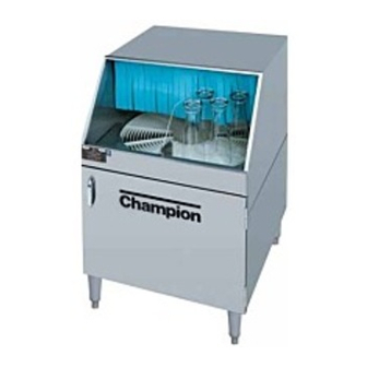
Rotary-type
Conveyor Glasswasher
Models:
CGM7 Clockwise Rotation
(access door front)
CGM7-1 Clockwise Rotation
(access door right)
CGM7-2 Counter-Clockwise
(access door left)
Glasswasher serial no.
Issue Date: 7.7.08
Manual P/N 0512652 rev. A
For machines beginning with S/N G080410261
Printed in the USA
Advertisement
Table of Contents

Related Manuals for Champion CGM7


Summary of Contents for Champion CGM7
- Page 1 Installation Manual with Service Replacement Parts Rotary-type Conveyor Glasswasher Models: CGM7 Clockwise Rotation (access door front) CGM7-1 Clockwise Rotation CGM7 (access door right) clockwise rotation (access door front) CGM7-2 Counter-Clockwise (access door left) CGM7-1 clockwise rotation (access door right) Glasswasher serial no.
- Page 2 "The 'USGBC Member Logo' is a trademark owned by the U.S. Green Building Council and is used by permission. The logo signifies only that Moyer Diebel is a USGBC member; USGBC does not review, certify or endorse the products or services offered by its members."...
- Page 3 ATTENTION: glass...
- Page 5 information that was not available at print time. We reserve the right to make changes to this manual without notice and without incurring any liability by making the changes. Glasswasher owners may request a revised manual, at no charge, by calling (800.858.4477) in the USA or (800.263.5798) in Canada.
- Page 6 Dear Owner: Thank you for choosing our glasswasher. We appreciate your business. This manual covers: Model CGM7 Rotary-Type Glasswasher, Clockwise Conveyor Rotation (access door front) Model CGM7-1 Rotary-Type Glasswasher, Clockwise Conveyor Rotation (access door right) Model CGM7-2 Rotary-Type Glasswasher, Clockwise Conveyor Rotation...
-
Page 7: Table Of Contents
Revision Record ......................Limited Warranty ......................CGM7 Rotary-type Conveyor Glasswasher Installation ----------------------------------------------------------------------------------- 1 Unpacking -------------------------------------------------------------------------------------- 1 Utility Connections --------------------------------------------------------------------------- 3 Chemicals -------------------------------------------------------------------------------------- 4 Operation ------------------------------------------------------------------------------------- 6 Cleaning ------------------------------------------------------------------------------------- 9 Troubleshooting ----------------------------------------------------------------------------- 10 Service Replacement Parts -------------------------------------------------------------- 15 Electric Schematic -------------------------------------------------------------------------- 40... -
Page 8: Limited Warranty
"The Company" and installed within the United States and Canada to be free from defects in material and workman ship for a period of one (1) year after the date of installation or fifteen (15) months after the date of shipment by "The Company", whichever occurs first. -
Page 9: Installation
Remove (2) 1/2-13 x 2" bolts holding the glasswasher to the pallet. Lift the front door off the bottom hinges and set carefully aside. The illustrations below show one method to install the legs without lifting the glasswasher completely off the pallet. - Page 10 Use 2 people to move the machine in order to install the legs. Have 1 person behind the glasswasher tilt it back as the person in front twists the machine to the right. This makes the front left leg mounting hole accessible.
-
Page 11: Utility Connections
Maximum drain flow 3 US gallons/min [11L/min] Electric Connection: Side View 208-230VAC/50-60HZ/1PH Min/Max 15A 6 ft. /1.5 m flexible cord and plug supplied NEMA 6-15P electric outlet 39" [991] 7¼" [184] Contact the Manufacturer's National Service Dept. for assistance. 8¾" [222]... -
Page 12: Chemicals
Rinse-aid Consult your chemical supplier for the proper type of rinse-aid to use in the glasswasher. Installing chemical supply containers and chemical pick-up tubes There is enough space inside the lower compartment to hold 3 one gallon containers for detergent, sanitizer, and rinse-aid. - Page 13 Each chemical injector can be adjusted using its prime button and concentration adjusting screw. These controls are located on the right side of the control box located in the lower compartment of the glasswasher. The white injector rotors are visible through the control box window.
-
Page 14: Operation
Operation Flow Diagram The diagram below shows the major components of the DFM7 glasswasher and the flow of water and chemicals during normal operation. - Page 15 A wash tank in the lower compartment holds heated wash water. The water level in the wash tank is maintained by a float and cam-operated switch. The wash tank water temperature is controlled by a heater and a thermostat.
-
Page 16: Filling The Wash Tank
Make sure the power switch is in the OFF position. • Install the wash arms and rinse spray arms. The spray arms have locating notches in the end of each arm. Push the spray arm straight into the hub. Do not twist. • Install the conveyor assembly as follows: Insert the conveyor into the wash chamber keeping the rear raised. -
Page 17: Cleaning
Pull (1) assembly at a time. Check the black O-ring on the spray tube hub for damage, replace if missing. 9. Insert and twist the small brass drill bit (reamer) in the each spray tube hole to clean. Insert and twist the large drill on the wood handle. -
Page 18: Troubleshooting
Troubleshooting The following troubleshooting guide can help identify a problem and provide a solution. Inspect your glasswasher before you contact an authorized service representative. Problem Cause(s) Solution(s) Glasswasher will not turn ON. Turn breaker/fuse box ON. Main breaker/fuse box OFF Disconnect fuse blown/breaker Turn breaker/fuse box ON. tripped. Replace fuse/Reset Breaker. Glasswasher ON/OFF switch Flip ON/OFF switch ON. OFF. Power cord unplugged. Plug-in power cord. - Page 19 Troubleshooting Problem Cause(s) Solution(s) Splash curtain is missing, Re-install the splash curtain or Water sprays out the front of the positioned incorrectly or damaged. replace the splash curtain. glasswasher. Spray arm(s) are damaged or Replace spray arm(s). missing. Reload glass(es).
- Page 20 Detergent tank thermostat tem- Water temperature below 145°F/66°C perature setting low. 145°F/66°C in detergent tank. Authorized service agent may Thermostat is defective. replace thermostat. Detergent tank heater is defective. Authorized service agent may replace detergent tank heater. Incoming water temperature is Raise incoming below 140°F/60°C. water temperature to 140°F/60°C.
- Page 21 Rinse water pressure too high measured at the glasswasher the glasswasher. below 95 psi [655 kPa]. Refill the container(s). Chemical container(s) are empty. Remove the supply line(s) from the Chemical supply line(s) are chemical containers and flush with clogged. warm water. Replace supply line(s) and/or pump Chemical supply and/or pump tube(s).
- Page 22 Blank Page This Page Intentionally Left Blank...
-
Page 23: Service Replacement Parts
Service Replacement Parts Service Replacement Parts... - Page 24 Base Assembly...
- Page 25 Qty. Part Description 112519 Cap Plug, 1" 0501885 Magnetic Door Catch 0712644 Wash Tank Scrap Screen 0312608 Wash Tank Scrap Screen Handle 0501873 Leg 6" 0712643 Door Assy. 0501921 Door Handle 100007 Screw, 1/4-20 X1/2" truss head 0712647 Door Bracket Assy.
- Page 26 Conveyor, Guides, Curtains...
- Page 27 Conveyor, Guides, Curtains Item Qty. Part Description 0312603 Conveyor Hub 0312695 Conveyor Guide Block 0312604 Conveyor Tray 0506886 Drive Gear 0506885 Conveyor 0312610 Curtain Rod (3/8"D x 24"L) 0512549 Curtain...
- Page 28 Wash Hubs, Spray Arms upper wash spray arm upper rinse spray arm notch in center notch on right CGM7 and CGM7-1 Clockwise conveyor rotation Shown lower rinse spray arm lower wash spray arm notch on left notch in center...
- Page 29 0300908 3/8" SST Tube Note: * Wash and rinse spray arms have notches to make sure they are installed correctly. The illustration on page 20 is for the clockwise conveyor rotation Models CGM7, and CGM7-1. The CGM7-2 conveyor rotation is counter-clockwise.
- Page 30 Conveyor Stop Switch...
- Page 31 Screw 10-32 x 3/8" 0712648 Shut-off Arm Assy. 0512555 Conveyor Shut-off Shaft 0512559 Spring 0512557 Conveyor Shut-off Cam 0510854 Dog-point Screw 1/4-20 x 1/2" 0510493 Carriage Bolt 10-24 x 1/2" 0312605 Switch nut plate 0501379 Switch 15A 0501437 Screw 4-40 x 1/2" ____...
- Page 32 Drive Motor Assembly...
- Page 33 Drive Motor Assembly Item Qty. Part Description 0506886 Drive Gear 0507264 Water Slinger 0501923 Extension Spring 0512713 Snap Bushing 0501412 Screw 10-32 x 3/8" 0307617 Drive Motor Housing Cover 0512532 Drive Motor 0712712 Drive Motor Housing...
- Page 34 Vacuum Breaker Assembly...
- Page 35 Item Qty. Part Description 0502665 1/2" I.D. Braided Hose 0503679 7/16" Gear Clamp 0502653 3/8" MPT x 1/2" MPT Hose Barb 100500 1/2" Vacuum Breaker 0508366 Vacuum Breaker Repair Kit 0502651 1/2" MPT x 1/2" Hose barb 0312684 Plumbing Support 106026 Washer, Flat 1/4"...
- Page 36 Wash Pump and Piping...
- Page 37 0502563 Hose Clamp #6 6" 0502668 Braided Hose 1" ID 0501632 Pump Hose Connector 0503679 Hose Clamp #16 0502665 Braided Hose 1/2" 0502663 Braided Hose 3/8" * Note: The pump motor is not available as a separate service replacement part.
- Page 38 Inlet Plumbing To Vacuum Breaker To Detergent Tank Cold Water Valve Hot Water Valve Water solenoid detail...
- Page 39 3/8” MPT Tee 0503801 3/8” Fem x 1/2” Adapter 0507324 3/8” Check Valve 0502768 Mixing Valve 0502653 3/8” x 1/2’ 90º Hose Barb 0503679 7/16” Gear Clamp 0502665 1/2” I.D. Braided Hose 0509659 Brass Cap 0504822 Screw 8-32 x 1/2”...
- Page 40 Sanitizer Plumbing...
- Page 41 1/2" x 1/2" x 3/8" Tee 0503669 Injector Barb Fitting 0501519 Cable Tie 4" 0502666 Chemical Tubing 1/8" IDx1/4"OD 0502653 3/8" MPT x 1/2" 90° Hose Barb 0503668 Thermometer 0502577 3/8 x 1/4" Reducer Bushing 0502583 3/8" FPT Cross Connector 0507100...
- Page 42 Detergent tank Assembly To control box...
- Page 43 Detergent Tank 0307427 Water Inlet Tube 0503679 Hose Clamp #6 0502665 Braided Hose 1/2" 6" 0502668 PVC Hose 1" ID x 1-3/8" OD 0502563 Gear Clamp 1" 108051 Elbow Flange 0507431 Bolt M6 x 25mm (metric) 107886 Inlet Chute Gasket...
- Page 44 Control Box Assembly To glass washer From chemical container Rinse-aid Sanitizer Detergent...
- Page 45 Control Box Assembly Item Qty. Part Description 0501353 Injector Motor, 140RPM 12VDC 0707142 Injector Rotor Assembly 0706635 Element Tube 45CC (DET, SANI) 0706634 Element Tube 15CC (R/A) 0503695 Chemical Tube Detergent Label ------ 0503694 Chemical Tube Sanitizer Label ------ 0505483...
- Page 46 Options And Accessories...
- Page 47 Hose, 1/2 male quick disconnect, 16" – 0707258 Quick Disconnect Package (including casters) – 0701962 Caster Kit (2 Locking, 2 Regular) – 0708453 Hand Sink and Wet Waste Receiver (SW46) – 0701956 Wash Down Hose (includes items 4 - 8) – 0703454 Wash Down Nozzle...
-
Page 48: Electric Schematic
Electric Schematic...
Need help?
Do you have a question about the CGM7 and is the answer not in the manual?
Questions and answers