Table of Contents

Related Manuals for Champion CTD-1800H


Summary of Contents for Champion CTD-1800H
- Page 1 Champion The Dishwashing Machine Specialists Technical Manual No Heat Tray Dryer Model CTD-1800H November, 1992 111483 P.O. Box 4149 Winston-Salem, North Carolina 27115-4149 Champion Industries, Inc. 919/661-1556 FAX:919/661-1660...
-
Page 2: Table Of Contents
CONTENTS Page WARRANTY INTRODUCTION GENERAL INSTALLATION Unpacking Electrical Connections Plumbing Connections Completing Installation OPERATION MAINTENANCE Maintenance Schedule Deliming TROUBLESHOOTING REPLACEMENT PARTS LIST OF FIGURES Figure 1— Load Access Cover/Stan-Stop Assembly Figure 2— Drive Assembly Figure 3— Tray Accumulator Assembly Figure 4— Shaft/Belt Assembly (Upper) Figure 5—... -
Page 3: Warranty
Warranty of Machines: Champion warrants all new machines of its manufacture bearing the name "Champion" and installed within the United States to be free from defects in material and workmanship for a period of one (1) year after the dale of installation or fifteen (15) months after the date of shipment by Champion, whichever occurs first. (Sec below for special provisions relating to glasswashers.] The warranty registration card must be returned to Champion within ten (10) days after... -
Page 4: Introduction
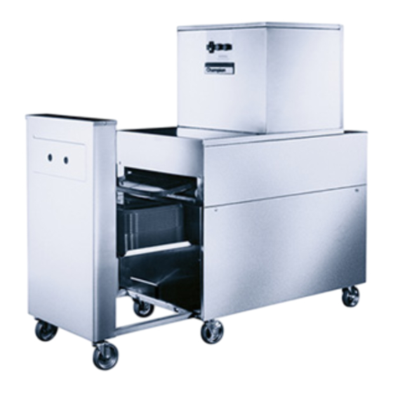
INTRODUCTION Welcome to Champion. Thank you for choosing Champion and for allowing us to take care of your tray drying needs. This manual covers the model CTD-1800H. Your machine has been completely assembled, inspected, and thoroughly tested at our factory to eliminate problems at installation before it was shipped to your installation site. -
Page 5: General
-Power cords with a 240V, 30A plug accumulator shut-off) -Easily removable filter -Portable (casters) This model tray dryer, CTD-1800H, has a maximum drying speed of 1800 trays per hour (based on a 14 inch by 18-inch tray). Options - Machine Electrical Options: •... -
Page 6: Installation
INSTALLATION Unpacking 1. Immediately after unpacking your machine, inspect it for any shipping damage. If damage is found, save the packing material and contact the carrier within 10 days. 2. Remove the tray dryer from the skid. Move it to the desired location. Electrical Connections 1. -
Page 7: Plumbing Connections
Plumbing Connections 1. The tray dryer is supplied with a gravity drain and a 1 -1 /4 inch I.D. flexible drain hose (located near the load end of the unit). The end of the drain hose is approximately 3 inches above the floor. The drain water should be directed to a floor drain. -
Page 8: Operation
OPERATION The operation of your tray dryer will be more efficient when these procedures are followed: 1. Check that the filter holder assembly is in place. It is located at the unload end of the dryer. 2. Push the power switch to the ON position. 3. -
Page 9: Maintenance
MAINTENANCE The efficiency and life of your machine is increased by regularly scheduled preventive maintenance. A well-maintained machine gives better results and service. An investment of a minutes of daily maintenance will be worthwhile. The best maintenance you can provide is to keep your machine clean. Components that are not regularly cleaned will clog and become inoperative. -
Page 10: Deliming
•Weekly 1. Wash the air intake filter. 2. Clean the exterior of the machine of all foreign residue. 3. Check the alignment of the belt on the pulleys. 4. Check all bearings for free rotation. Grease the bearings using the fittings provided. Deliming Depending on the mineral content of your water, your tray dryer may need deliming. -
Page 11: Troubleshooting
TROUBLESHOOTING Before determining any specific cause of a breakdown or abnormal operation of your tray dryer, check that: 1. Power switch is ON 2. Tray accumulator is not full. If a problem still exists, use the following table for troubleshooting. CONDITION CAUSE SOLUTION... -
Page 12: Replacement Parts
Figure 1—Load Access Cover/Start-Stop Assembly... - Page 13 LOAD ACCESS COVER/START-STOP ASSEMBLY Part Fig. 1 Part Description Qty. Item No. 110817 Contact Block. N.O. (Start) 110818 Contact Block. N.C. (Stop) 100007 Screw. 10-32 x 3/8" Hex Head 111317 Name Decal 108390 Rivet. Pop 3/32" 110815 Pushbutton - (Red) - Stop 110814 Pushbutton - (Green) - Start 110843...
-
Page 14: Figure 2- Drive Assembly
Figure 2 – Drive Assembly... - Page 15 DRIVE ASSEMBLY Fig. 2 Part Part Description Qty. Item No. 107966 Nut. Grip 10-32 w/nylon insert 106486 Washer. Lock. #10 Split 107033 Washer, Flat. #10 106026 Washer. Flat. 1/4" 105254 Boll, 10-32 x 1/2" Hex Head 316602 Splash Guard 111420 Belt, Drive D-367L050 100770 Screw, Set 10-32 x 3/8"...
-
Page 16: Figure 3-Tray Accumulator Assembly
Figure 3—Tray Accumulator Assembly... - Page 17 TRAY ACCUMULATOR ASSEMBLY Fig. 3 Part Part Description Qty. Item No. 315919 Bracket. Limit Switch 106482 Washer. Lock 1/4" Split 100734 Bolt. 1/4-20 x 1/2" Hex Head 100097 Screw. 10-32 x 1/2" Truss Head 107341 Switch, Limit #ZCKL1 111075 Head. Limit Switch 111074 Wand, Limit Switch 107967...
-
Page 18: Figure 4-Shaft/Belt Assembly (Upper)
Figure 4—Shaft/Belt Assembly (Upper) - Page 19 SHAFT/BELT ASSEMBLY (UPPER) Fig. 4 Part Part Description Qty. Item No. 204812 Bearing. Block, 3/4" Bore Nickel-Plated 100771 Screw, Set 1/4-20 x 1/4" Cup Point 102376 Washer. Flat. 5/16" 106013 Washer. Lock 5/16" Split 100740 Boll, 5/16-18 x1" Hex Head 104917 Key 3/16"...
-
Page 20: Figure 6- Blower/Duct Assembly - Lower
Figure 6 – Blower/Duct Assembly - Lower... -
Page 21: Figure 5- Shaft/Belt Assembly (Lower)
SHAFT/BELT ASSEMBLY (LOWER) Fig. 5 Part Part Description Qty. Item No. 204812 Bearing, Block, 3/4" Bore Nickel-Plated 100771 Screw. Set 1/4-20 x 1/4" Cup Point 102376 Washer. Flat. 5/16" 106013 Washer. Lock 5/16" Split 100740 Boll. 5/16-18 x 1" Hex Head 104917 Key 3/16"... - Page 23 BLOWER/DUCT ASSEMBLY (LOWER) Fig. 6 Part Part Description Qty. Item No. 316641 Duct. Blower 100735 Bolt. 1/4-20 x 5/8" Hex Head 111417 Gasket. Duct 100141 Nut, Grip 1/4-20 111416 Blower Assy. Bottom (Includes item #11) 106026 Washer. Flat 1/4" 100740 Bolt.
-
Page 24: Figure 7-Upper Panel/Unload Access Door Assembly
Figure 7—Upper Panel/Unload Access Door Assembly... - Page 25 UPPER PANELS/UNLOAD ACCESS DOOR ASSEMBLY Fig. 7 Part Part Description Qty. Item No. 316606 Panel, Top 100211 Screw. 10-32 x 1" Truss Head 316607 Panel. End 316699 Access Door. Unload 100213 Screw. 10-32 x 1/4" Truss Head 205035 Hinge, Access Door 100194 Nut.
-
Page 27: Figure 8- Blower & Duct Assembly (Upper)
BLOWER & DUCT ASSEMBLY (UPPER) Fig. 8 Part Part Description Qty. Item No. 316641 Duct, Blower 100141 Nut, Grip 1/4-20 111417 Gasket. Duct 106026 Washer, Flat 1/4" 100735 Boll. 1/4-20 x 5/8" Hex Head 111415 Blower Assy. Upper (Includes item #7) 111455 Motor, 3HP 208V-240V-60Hz-3PH 100740... -
Page 28: Figure 9-Hood Base/Panel Assembly
Figure 9—Hood Base/Panel Assembly... - Page 29 HOOD/BASE/PANEL ASSEMBLY Fig. 9 Part Part Description Oty. Item No. 304816 Strainer, Drain Body 107863 Drain Body 107864 Washer. Drain Body 105286 Screw, 1/4-20 x 1" Truss Head 316626 Panel. Load End 107865 Nut, Drain Body 107866 Washer. Tail Piece 109283 Tailpiece 107867...
-
Page 30: Figure 10-Panel Assembly, Tray Accumulator
Figure 10—Panel Assembly, Tray Accumulator... - Page 31 PANEL ASSEMBLY, TRAY ACCUMULATOR Fig. 10 Part Part Description Qty. Item No. 316649 Panel, Center 100781 Screw, 1/4-20 x 1/2" Truss Head 316650 Panel, Top 315585 Access Door 108966 Handle, Access Door 316651 Panel, Skirt 106460 Screw, 6-32 x 1/4" Truss Head...
-
Page 32: Figure 11- Electrical Control Panel
Figure 11 – Electrical Control Panel... - Page 33 Electrical Control Panel Fig. 11 Part Part Description Qty. Item No. 106472 Bolt. 1/4-20 x 1-1/4" Truss Head 110900 End Plate 110812 Bus Bar - 3 Pole 307467 Control Box 316685 Inner Panel 307470 Cover, Control Box 100007 Screw. 10-32 x 3/8" Truss Head 108272 Terminal Strip 111068...
-
Page 34: Figure 12- Wiring Diagram
Figure 12 – Wiring Diagram...
Need help?
Do you have a question about the CTD-1800H and is the answer not in the manual?
Questions and answers