
Related Manuals for FS S3250 Series


Summary of Contents for FS S3250 Series
- Page 1 S3250 SERIES POE+ SWITCHES POE+-SWITCHES DER SERIE S3250 SWITCHS POE+ SÉRIE S3250 S����シリーズPOE+スイッチ Quick Start Guide V1.0 Quick Start Anleitung Guide de Démarrage Rapide クイックスタートガイド...
- Page 2 Introduction Thank you for choosing the S3250 Series PoE+ Switches. This guide is designed to familiari ze you with the layout of the switches and describes how to deploy them in your network. S3250-16TF-U S3250-24TF-U Accessories Power Cord x1 Mounting Bracket x2...
-
Page 3: Hardware Overview
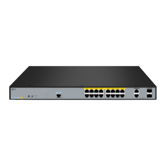
Hardware Overview Front Panel Ports S3250-16TF-U Console RJ45 Combo S3250-24TF-U Console RJ45 Combo Ports Description 10/100/1000BASE-T ports for Ethernet connection. Ports 1~16/1~24 RJ45 support the PoE function Combo One RJ45 port and one SFP port, with one port active at a time Console An RJ45 console port for serial management Front Panel LEDs... - Page 4 S3250-24TF-U RJ45 (1~24) MODE LED RJ45 (25T~26T) SFP (25S~26S) PoE (1~24) LEDs State Description The switch is powered o . Solid Green The switch is powered on. The switch is powered o . The switch system is starting or the switch MODE LED Solid Green LED is in Link/Act/Speed mode.
-
Page 5: Front Panel Buttons
Front Panel Buttons S3250-16TF-U RESET MODE S3250-24TF-U RESET MODE Buttons Description MODE Switch to the PoE mode. RESET Press it to restore factory default settings. Installation Requirements Before the installation, make sure that you have the following conditions ready: Phillips screwdriver, M6 screws and cage nuts. Standard-sized, 19"... -
Page 6: Site Environment
Site Environment Place the switch on a stable place or on a desktop to prevent it from falling and breaking. Make sure that the power supply voltage is consistent with the voltage marked on the switch. The switch can only work properly when powered by the correct power supply. To keep the switch away from electrical sparks, do not open the switch casing, even when it is not powered on. -
Page 7: Rack Mounting
Rack Mounting 1. Secure the mounting brackets to the two sides of the switch with M3 screws. 2. Attach the switch to the rack using M6 screws and cage nuts. -
Page 8: Grounding The Switch
Grounding the Switch AC LIN E 10 0-2 40 VA 50 /6 0H z 1. Connect one end of the grounding cable to a proper earth ground, such as the rack in which the switch is mounted. 2. Secure the grounding lug to the grounding point on the switch with the washers and the screw. -
Page 9: Connecting The Sfp Ports
Connecting the RJ45 Ports 1. Connect an Ethernet cable to the RJ45 port of a network device. 2. Connect the other end of the Ethernet cable to the RJ45 port of the switch. Connecting the SFP Ports 1. Plug the compatible SFP transceiver into the SFP port. 2. -
Page 10: Connecting The Console Port
Connecting the Console Port 1. Insert the RJ45 connector into the RJ45 console port on the switch. 2. Connect the DB9 female connector of the console cable to the serial port on the computer. Connecting the Power AC LI NE 10 0- 24 0V 50 /6 0H z 1. - Page 11 Con guring the Switch Con guring the Switch Using the Web-Based Interface Step 1: Connect a computer to the Ethernet port of the switch using the network cable. Step 2: Set the IP address of the computer to 192.168.1.x ("x" is any number from 2 to 254). Step 3: Open a browser, type http://192.168.1.1 and enter the default username and password, admin/admin.
- Page 12 Con guring the Switch Using the Console Port Step 1: Connect a computer to the console port of the switch with the console cable. Step 2: Start the terminal simulation software, such as HyperTerminal on the computer. Step 3: Set the parameters of the HyperTerminal: Baud rate to 115200, Data bits to 8, Parity to None, and Stop bits to 1.
-
Page 13: Troubleshooting
Troubleshooting Forgetting the Username and Password 1. Connect the serial port of the con guration computer to the console port of the switch, and open the HyperTerminal. 2. Power o and restart the switch. When Press CTRL-B to enter the bootUtil is displayed on the HyperTerminal interface, press Ctrl + B to enter the bootUtil menu. -
Page 14: Product Warranty
Product Warranty FS ensures our customers that for any damage or faulty items due to our workmanship, we will o er a free return within 30 days from the day you receive your goods. This excludes any custom-made items or tailored solutions. - Page 15 Einführung Vielen Dank, dass Sie sich für die PoE+-Switches der Serie S3250 entschieden haben. Diese Anleitung soll Sie mit dem Aufbau der Switches vertraut machen und beschreibt, wie Sie sie in Ihrem Netzwerk einsetzen. S3250-16TF-U S3250-24TF-U Zubehör Netzkabel x1 Montagehalterung x2 Gummipad x4 M3-Schraube x8 HINWEIS:...
-
Page 16: Leds An Der Vorderseite
Hardware-Übersicht Ports an der Vorderseite S3250-16TF-U Console RJ45 Combo S3250-24TF-U Console RJ45 Combo Ports Beschreibung 10/100/1000BASE-T-Ports für Ethernet-Verbindungen. Die Ports RJ45 1~16/1~24 unterstützen die PoE-Funktion. Ein RJ45-Port und ein SFP-Port, wobei jeweils nur ein Port aktiv sein Combo kann. Console Ein RJ45-Console-Port für die serielle Verwaltung LEDs an der Vorderseite S3250-16TF-U... - Page 17 S3250-24TF-U RJ45 (1~24) MODE LED RJ45 (25T~26T) SFP (25S~26S) PoE (1~24) LEDs Status Beschreibung Der Switch ist ausgeschaltet. Durchgehend grün Der Switch ist eingeschaltet. Der Switch ist ausgeschaltet. Das Switch-System wird gestartet oder Durchgehend grün die LED des Switches be ndet sich im MODE LED Link/Act/Speed-Modus.
- Page 18 LEDs Status Beschreibung Ein PD ist mit dem entsprechenden Port 1~16/1~24 Durchgehend grün verbunden. Die PoE-Stromversorgung ist ordnungsgemäß. Tasten an der Vorderseite S3250-16TF-U RESET MODE S3250-24TF-U RESET MODE Tasten Beschreibung MODE Auf den PoE-Modus umschalten. RESET Diese Taste drücken, um die Werkseinstellungen wiederherzustellen. Installationsvoraussetzungen Vergewissern Sie sich vor der Installation, dass Sie Folgendes bereithalten:...
- Page 19 Standortumgebung Stellen Sie den Switch an einem stabilen Ort oder auf einer Arbeits äche auf, damit er nicht herunterfallen und zerbrechen kann. Stellen Sie sicher, dass die Versorgungsspannung mit der auf dem Switch angegebenen Spannung übereinstimmt. Der Switch kann nur dann ordnungsgemäß funktionieren, wenn er von der richtigen Stromversorgung gespeist wird.
- Page 20 Rack-Montage 1. Befestigen Sie die Montagehalterungen mit M3-Schrauben an den beiden Seiten des Switches. 2. Befestigen Sie den Switch mit M6-Schrauben und M6-Kä gmuttern am Rack.
- Page 21 Erdung des Switches AC LIN E 10 0-2 40 VA 50 /6 0H z 1. Schließen Sie ein Ende des Erdungskabels an eine geeignete Erdung an, z. B. an das Rack, in dem der Switch montiert ist. 2. Befestigen Sie die Erdungslasche mit den Unterlegscheiben und der Schraube am Erdungspunkt des Switches.
- Page 22 Anschließen der RJ45-Ports 1. Schließen Sie ein Ethernet-Kabel an den RJ45-Port eines Netzwerkgeräts an. 2. Schließen Sie das andere Ende des Ethernet-Kabels an den RJ45-Port des Switches an. Anschließen der SFP-Ports 1. Verbinden Sie den kompatiblen SFP-Transceiver mit dem SFP-Port. 2.
-
Page 23: Anschließen Der Stromversorgung
Anschließen des Console-Ports 1. Stecken Sie den RJ45-Steckverbinder in den RJ45-Console-Port des Switches. 2. Verbinden Sie die DB9-Buchse des Console-Kabels mit dem seriellen Port des Computers. Anschließen der Stromversorgung AC LI NE 10 0- 24 0V 50 /6 0H z 1. - Page 24 Kon gurieren des Switches Kon gurieren des Switches mithilfe der webbasierten Schnittstelle Schritt 1: Schließen Sie einen Computer über ein Netzwerkkabel an den Ethernet-Port des Switches an. Schritt 2: Stellen Sie die IP-Adresse des Computers auf 192.168.1.x ein („x“ ist eine beliebige Zahl zwischen 2 und 254).
- Page 25 Kon gurieren des Switches über den Console-Port Schritt 1: Schließen Sie einen Computer über das Console-Kabel an den Console-Port des Switches an. Schritt 2: Starten Sie die Terminalsimulationssoftware, z. B. HyperTerminal, auf dem Computer. Schritt 3: Stellen Sie die Parameter von HyperTerminal ein: Baud Rate auf 115200, Data Bits auf 8, Parity auf None und Stop Bits auf 1.
-
Page 26: Fehlerbehebung
Fehlerbehebung Benutzername und Passwort vergessen 1. Verbinden Sie den seriellen Port des Kon gurationscomputers mit dem Console-Port des Switches, und ö nen Sie HyperTerminal. 2. Schalten Sie den Switch aus und starten Sie ihn neu. Wenn auf der HyperTerminal- Ober äche Press CTRL-B to enter the bootUtil angezeigt wird, drücken Sie Strg + B, um das Menü... - Page 27 Produktgarantie FS garantiert seinen Kunden, dass wir bei Schäden oder fehlerhaften Artikeln, die auf unsere Verarbeitung zurückzuführen sind, eine kostenlose Rückgabe innerhalb von 30 Tagen nach Erhalt der Ware anbieten. Dies gilt nicht für Sonderanfertigungen oder maßgeschneiderte Lösungen. Garantie: Für das Produkt gilt eine eingeschränkte Garantie von 4 Jahren auf Material- und Verarbeitungsfehler.
- Page 28 Introduction Nous vous remercions d'avoir choisi les switchs PoE+ de la série S3250. Ce guide est conçu pour vous familiariser avec la disposition des switchs et décrit comment les déployer dans votre réseau. S3250-16TF-U S3250-24TF-U Accessoires Cordon d'alimentation x1 Support de montage x2 Coussin en caoutchouc x4 Vis M3 x8 NOTE :...
-
Page 29: Aperçu Du Matériel
Aperçu du Matériel Ports du Panneau Frontal S3250-16TF-U Console RJ45 Combo S3250-24TF-U Console RJ45 Combo Ports Description Ports 10/100/1000BASE-T pour la connexion Ethernet. Les ports RJ45 1~16/1~24 prennent en charge la fonction PoE. Combo Un port RJ45 et un port SFP, avec un port actif à la fois Console Un port de console RJ45 pour la gestion en série LED du Panneau Frontal... - Page 30 S3250-24TF-U RJ45 (1~24) MODE LED RJ45 (25T~26T) SFP (25S~26S) PoE (1~24) LEDs State Description Éteint Le switch est hors tension. Vert solide Le switch est sous tension. Éteint Le switch est hors tension. Le système du switch démarre ou le MODE LED Vert xe voyant du switch est en mode Link/Act/...
-
Page 31: Exigences D'installation
LEDs State Description Un PD est connecté au port 1~16/1~24 Vert xe correspondant, et l'alimentation PoE est normale. Boutons du panneau frontal S3250-16TF-U RESET MODE S3250-24TF-U RESET MODE Buttons Description MODE Switchs vers le mode PoE. RESET Appuyez sur cette touche pour rétablir les paramètres d'usine par défaut. Exigences d'installation Avant de procéder à... - Page 32 Environnement du site Placez l'interrupteur sur un endroit stable ou sur un bureau pour éviter qu'il ne tombe et ne se brise. Assurez-vous que la tension d'alimentation correspond à la tension indiquée sur l'interrupteur. Le switch ne peut fonctionner correctement que s'il est alimenté par la bonne alimentation.
-
Page 33: Montage En Rack
Montage en rack 1. Fixez les supports de montage sur les deux côtés du switch à l'aide de vis M3. 2. Fixez le switch au rack à l'aide de vis M6 et d'écrous à cage. - Page 34 Mise à la terre du switch AC LIN E 10 0-2 40 VA 50 /6 0H z 1. Connectez une extrémité du câble de mise à la terre à une terre appropriée, telle que le rack dans lequel le switch est monté. 2.
- Page 35 1. Connectez un câble Ethernet au port RJ45 d'un périphérique réseau. 2. Connectez l'autre extrémité du câble Ethernet au port RJ45 du switch. Connexion des ports SFP 1. Branchez l'émetteur-récepteur SFP compatible dans le port SFP. 2. Connectez un câble à bre optique à l'émetteur-récepteur à bre. Connectez ensuite l'autre extrémité...
-
Page 36: Raccordement De L'alimentation
Connexion du Port Console 1. Insérez le connecteur RJ45 dans le port de console RJ45 du switch. 2. Branchez le connecteur femelle DB9 du câble de console au port série de l'ordinateur. Raccordement de l'alimentation AC LI NE 10 0- 24 0V 50 /6 0H z 1. - Page 37 Con guration du switch Con guration du switch à l'aide de l'interface Web Étape 1 : Connectez un ordinateur au port Ethernet du switch à l'aide du câble réseau. Étape 2 : Réglez l'adresse IP de l'ordinateur sur 192.168.1.x ( x est un nombre quelconque compris entre 2 et 254).
- Page 38 Con guration du switch à l'aide du port de console Étape 1 : Connectez un ordinateur au port de console du switch à l'aide du câble de console. Étape 2 : Lancez le logiciel de simulation de terminal, tel que HyperTerminal sur l'ordinateur. Étape 3 : Dé...
-
Page 39: Dépannage
Dépannage Oubli du nom d'utilisateur et du mot de passe 1. Connectez le port série de l'ordinateur de con guration au port de console du switch, et ouvrez HyperTerminal. 2. Mettez le switch hors tension et redémarrez-le. Lorsque Press CTRL-B to enter the bootUtil s'a che sur l'interface HyperTerminal, appuyez sur Ctrl + B pour accéder au menu bootUtil. - Page 40 Garantie des produits FS garantit à ses clients que pour tout dommage ou article défectueux dû à notre travail, nous o rons un retour gratuit dans un délai de 30 jours à compter de la date de réception de la marchandise. Cette garantie ne s'applique pas aux articles fabriqués sur mesure ou aux solutions personnalisées.
- Page 41 イントロダクション このたびは、S����シリーズPoE+スイッチをお買いあげいただき、誠にありがとうござい ます。本ガイドは、S����シリーズスイッチの概要とネットワークへの導入方法について 説明します。 S����-��TF-U S����-��TF-U アクセサリー 電源コード x� 取付けブラケット x� ゴムパッド x� M�ネジ x� 注:付属品の図は参考用です。 注:この電源コードは他の機器には使用できません。また、他の電源コードはこ の機器に使用しないでください。...
- Page 42 ハードウェアの概要 フロントパネルのポート S����-��TF-U Console RJ�� Combo S����-��TF-U Console RJ�� Combo ポート 説明 イーサネット接続用��/���/����BASE-Tポート。ポート�~��/�~��は RJ�� PoE機能をサポート RJ��ポート×�、SFPポート×�(一度に�つのポートのみがアクティ Combo ブになります) Console シリアル管理用RJ��コンソールポート フロントパネルのLED S����-��TF-U RJ�� (�~��) MODE LED RJ�� (��T~��T) SFP (��S~��S) PoE (�~��)
- Page 43 S����-��TF-U RJ�� (�~��) MODE LED RJ�� (��T~��T) SFP (��S~��S) PoE (�~��) 状態 説明 消灯 スイッチの電源が切れています。 点灯(緑) スイッチの電源が入っています。 消灯 スイッチの電源が切れています。 スイッチ システムが起動中、またはスイッチの MODE LED 点灯(緑) LEDがLink/Act/Speedモードになっています。 点灯(橙) スイッの LEDはPoEモードになっています。 消灯 ポートはリンクされていません。 点灯(橙) ポートは��M/���Mでリンクされています。 ポートは��M/���Mでデータを送受信していま �~��/�~�� 点滅(橙) す。 点灯(緑) ポートは����Mでリンクされています。 RJ�� 点滅(緑) ポートは����Mでデータを送受信しています。...
- Page 44 フロントパネルのボタン S����-��TF-U RESET MODE S����-��TF-U RESET MODE ボタン 説明 MODE PoEモードに切り替えます。 RESET 押すと工場出荷時のデフォルト設定に戻ります。 設置要件 設置前に、以下の条件が整っていることを確認してください。 プラスドライバー、M�ネジとケージナット 高さ�U以上の標準サイズ��インチ幅ラック ネットワーク機器接続用カテゴリー�eまたはその以上のRJ��イーサネットケーブル、 光ファイバケーブル、コンソールケーブル。...
- Page 45 環境要件 スイッチの落下や破損を防ぐため、安定した場所やや卓上に置いてください。 電源電圧がスイッチに表示されている電圧と一致していることを確認してください。 スイッチは、正しい電源から給電されている場合にのみ正常に動作します。 スイッチを電気火花から遠ざけるため、電源が入っていないときでもスイッチのケーシ ングを開けないでください。 スイッチの放熱に十分な換気スペースがあることを確認してください。 ラックおよび作業台がスイッチと設置用の付属品の重量を支えるのに十分な強度がある ことを確認してください。 スイッチを清掃する前に、すべての電源コードをスイッチから取り外してください。 濡れた布で拭いたり、液体でクリーニングしたりしないでください。 スイッチの取り付け デスクマウント �. スイッチの底面に�つのゴムパッドを取り付けます。 �. スイッチを机の上に置きます。...
- Page 46 ラックマウント �. M�ネジで取付けブラケットをスイッチの両側に固定します。 �. M�ネジとケージナットを使用してスイッチをラックに取り付けます。...
- Page 47 スイッチの接地 AC LIN E 10 0-2 40 VA 50 /6 0H z �. アースケーブルの一端を、スイッチが取付けられているラックなどの適切な接地点に接 続します。 �. ワッシャーとネジを使用して、アースラグをスイッチの接地点に固定します。 注意:すべての電源接続が切断されていない限り、アース接続を取り外さないで ください。...
- Page 48 RJ��ポートの接続 �. イーサネットケーブルをネットワーク機器のRJ��ポートに接続します。 �. イーサネットケーブルのもう一方の端をスイッチのRJ��ポートに接続します。 SFPポートの接続 �. 互換性のあるSFPモジュールをSFPポートに接続します。 �. 光ファイバケーブルをファイバモジュールに接続します。次に、ケーブルのもう一方の 端を別のファイバデバイスに接続します。 注意:レーザー光線は目に損傷を与える可能性があります。保護メガネを着用せ ずに、光モジュールや光ファイバの穴を覗き込まないでください。...
- Page 49 コンソールボートの接続 �. RJ��コネクタをスイッチのRJ��コンソールポートに挿入します。 �. コンソールケーブルのDB�メスコネクタをPCのシリアルボートに接続します。 電源の接続 AC LI NE 10 0- 24 0V 50 /6 0H z �. AC電源コードをスイッチの電源ボートに接続します。 �. 電源コードのもう一方の端をAC電源に接続します。 警告:電源が入っている間は、電源コードを取り付けないでください。...
- Page 50 スイッチの設定 ウェブベースインターフェースによる設定 Step �:ネットワークケーブルを使用してコンピュータをスイイッチのイーサネットポー トに接続します。 Step �:コンピュータのIPアドレスを「���.���.�.x」( [x」は�~���の任意の数字)に設 定します。 Step �:ブラウザを開き、「http://���.���.�.�」と入力し、デフォルトのユーザー名 「admin」とパスワード「admin」を入力します。 Step �:「Login」をクリックすると、ウェブベースの設定ページが表示されます。...
- Page 51 コンソールポートからの設定 Step �:コンソールケーブルでコンピュータをスイッチのコンソールポートに接続します。 Step �:コンピュータ上でHyperTerminalなどのターミナルシミュレーションソフトウェ アを起動します。 Step �:HyperTerminalのパラメータでボーレート(Baud rate)を������、データビット (Data bits)を�、パリティ(Parity)をなし(None)、ストップビット(Stop bits)を�に 設定します。 Quick Connect Protocol: Serial The port may be manually entered or selected from the list. Port: COM5 USB Serial Port 115200 Baud rate: Flow Control DTR/DSR Data bits: RTS/CTS Parity: None...
- Page 52 トラブルシューティング ユーザー名/パスワードの紛失 �. 設定コンピュータのシリアルポートをスイッチのコンソールポートに接続し、ハイパー ターミナルを開きます。 �. スイッチの電源を切り、再起動します。ハイパーターミナルインターフェイスに 「Press CTRL-B to enter the bootUtil」と表示されたら、「Ctrl + B」を押してbootUtilメ ニューに入ります。 �. 「�」を入力して「Advanced menu」を選択し、パスワード「admin」を入力します。 �. 「Advanced menu」で「�」を選択してソフトウェアをリセットし、工場出荷時のデフ ォルト設定に戻します。 電源インジケータの異常 電源システムが正常に動作している場合、PWR LEDは常に点灯しているはずです。PWR LEDが点灯しない場合は、以下を確認してください。 �. スイッチの電源コードが正しく接続され、スイッチの電源ソケットに完全に差し込まれ ているか確認してください。 �. 電源がスイッチに必要な電力と一致しているか確認してください。 スイッチのWeb管理インターフェイスにログインできない �. スイッチでHTTP 管理ユーザー制限機能が有効になっており、現在のユーザー数が事前 に設定した上限に達している場合、アクセスが制限されます。後で再試行することをお勧 めします。 �. インジケータの状態を観察し、ポートケーブルが正しく接続されているか、ポートが無 効になっていないかを確認します。別の物理ポートを使用してスイッチにログインできま...
- Page 53 製品保証 FSは、カスタム製品又はカスタムソリューションを除き、当社の過失による製品の破損や 不良品があった場合、お客様が製品を受け取った日から��日以内に無料で返品、交換をす ることを保証します。 保証:この製品は、材料または製造上の欠陥に対して�年間の限定保証を提供し ます。保証の詳細については、下記のURLをご参照ください。 https://www.fs.com/jp/policies/warranty.html 返品/交換:返品及び交換を希望される場合、方法については下記のURLをご参 照ください。 https://www.fs.com/jp/policies/day_return_policy.html オンラインリソース その他の技術資料については、下記のURLをご参照ください。 https://www.fs.com/jp/products_support.html FSアプリをダウンロード QRコードを読み取り、App StoreまたはGoogle PlayストアからFSア プリをダウンロードしてインストールできます。若しくは下記のURL にアクセスしてください。 https://www.fs.com/jp/appdownload.html...
-
Page 54: Compliance Information
Compliance Information Note: This equipment has been tested and found to comply with the limits for a Class A digital device, pursuant to part 15 of the FCC Rules. These limits are designed to provide reasonable protection against harmful interference when the equipment is operated in a commercial environment. - Page 55 2014/35/EU, 2011/65/EU und (EU)2015/863. Eine Kopie der EU-Konformitätserklärung nden Sie unter www.fs.com/de/company/quality_control.html. FS.COM GmbH déclare par la présente que ce dispositif est conforme à la Directive 2014/30/EU, 2014/35/EU, 2011/65/EU et (EU)2015/863. Une copie de la Déclaration de Conformité de l'UE est disponible à l'adresse suivante https://www.fs.com/fr/company/quality_control.html.
- Page 56 Do not dispose of WEEE as unsorted municipal wasteand have to collect such WEEE separately. Q.C. PASSED Copyright © 2024 FS.COM All Rights Reserved.
Need help?
Do you have a question about the S3250 Series and is the answer not in the manual?
Questions and answers