Table of Contents
Advertisement
Quick Links
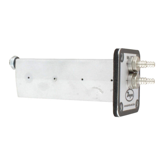
The Series MAFS Averaging Flow Sensor uses evenly distributed total
and static pressure measuring points to deliver an accurate
measurement of flows in a duct. The Air Flow Measuring Probe can be
completely installed from outside of the duct making it very easy to
install. With its lightweight and durable construction in addition to its
ease of installation, this product lends itself to being used in the HVAC
industry. These air flow measuring probes may be ordered to fit into
either round or rectangular duct installations.
INSTALLATION
When you unpack the Series MAFS Averaging Flow Sensor ensure that
there is no visible damage from shipping. Inspect each sensing point on
the probes to ensure that they are not filled with debris from shipping. If
there is obvious shipping damage, the probe must be replaced prior to
use in order to avoid inaccurate measurements. Please contact Dwyer
Instruments, Inc. if it is necessary to replace your air flow measurement
probe.
Location - The sensor should be installed in the flowing line with as
much straight run upstream as possible. A rule of thumb is to allow 10 -
15 diameters upstream and 5 downstream. The table below lists
recommended up and down piping.
CALCULATING VELOCITY
Air Velocity = 1096.2 (C p )
where:
P v = Sensed pressure difference (velocity pressure)
in inches of water column
D = Air density in lbs./ft. 3 (dry air = .075)
C p = Pitot tube coefficient: See specifications for
K-factor vs. size
Air Density = 1.325 X PB
P B = Barometric pressure in inches of mercury
T
= Absolute Temperature (Indicated Temperature in °F
plus 460)
DWYER INSTRUMENTS, INC.
P.O. BOX 373 • MICHIGAN CITY, INDIANA 46360, U.S.A.
Series MAFS Averaging Flow Sensor
Specifications - Installation and Operating Instructions
P v
D
T
1/2
[12.70]
1
APPROX.
1/4-20
[25.40]
THREADED
33/64
STUD
[12.95]
1-13/64
1-35/64
[30.44]
[39.37]
21/64
[8.46]
*L dimension = length of part designated in model.
SPECIFICATIONS
Service: Clean air.
Wetted Materials: Aluminum AA6063.
Accuracy: 0 to 9000 FPM (45.7 m/s); ±2% FS, ±3% FS for 6˝ and 48˝
length models.
K-Factor: 0.81, 0.80 for 6˝ and 48˝ lengths, 4˝ length=0.82.
Max. Temperature: 400°F (204°C); Gasket: -31 to 230°F (-35 to 110°C).
Minimum Design Flow: 400 fpm (2.03 m/sec).
Maximum Design Flow: 12,000 fpm (60.96 m/sec).
Process Connections: 1/4˝ barb.
Straight Run Requirements: 5 diameters or longest side dimensions.
RECTANGULAR DUCT MODELS
Determining Probe Number and Placement for Rectangular Ducts
1. To determine the number of probes you need please consult the
chart below.
Short Duct Dimension
Number of Probes
2. In order to determine where to place your probes, divide the short
duct dimension by number of probes.
3. Divide the result by two and this will be the distance from the top
edge of the duct to the first probe location.
4. The next probe will be placed two times the resulting distance from
step two from the first probe. So, if the first probe was placed 4˝ from
the top edge of the duct, your next probe would be placed 8" from the
first probe, or 12˝ from the top of the duct.
5. Continue this pattern until you have determined all probe locations.
Example: You have a duct with a 24˝ short side, and upon consulting the
chart determined that you needed 3 probes for this size duct.
24 / 3 = 8
8 / 2 = 4
Therefore, the first probe is placed 4˝ from the top of the duct.
The second probe is placed 4˝ + 8˝ = 12˝ from the top of the duct.
The third probe is placed 4˝ + (2 x 8˝) = 20˝ from the top of the duct.
Phone: 219/879-8000
Fax: 219/872-9057
Bulletin F-MAFS
4X Ø7/32
29/64
[Ø5.54]
[50.80]
1-11/32
[11.41]
[34.25]
33/64
[12.95]
1-1/2
1-3/64
[38.10]
[26.43]
1/4
[6.35]
L
1-1/2
1/4
49/64
[38.10]
[6.35]
[19.43]
<12˝
12˝ - 23˝
24˝ - 35˝
36˝ - 48˝
1
2
3
4
www.dwyer-inst.com
e-mail: info@dwyer-inst.com
2
2
[50.80]
Advertisement
Table of Contents

Related Manuals for Dwyer Instruments MAFS Series


Summary of Contents for Dwyer Instruments MAFS Series
- Page 1 The second probe is placed 4˝ + 8˝ = 12˝ from the top of the duct. The third probe is placed 4˝ + (2 x 8˝) = 20˝ from the top of the duct. DWYER INSTRUMENTS, INC. Phone: 219/879-8000 www.dwyer-inst.com P.O.
- Page 2 2. Locate probes 90 degrees apart. See Figure 2 for an example. 90° MAFS DAFM Figure 2: Cross-sectional view of probe placement in a round duct. ©Copyright 2012 Dwyer Instruments, Inc. Printed in U.S.A. 4/12 FR# 72-444019-00 Rev. 1 DWYER INSTRUMENTS, INC. Phone: 219/879-8000 www.dwyer-inst.com...
Need help?
Do you have a question about the MAFS Series and is the answer not in the manual?
Questions and answers