Advertisement
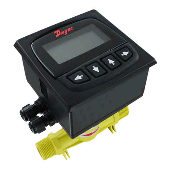
The Series DFMT Digital Paddlewheel Flow Transmitter provides
instantaneous, as well as totalizing flow monitoring, making it ideal for commercial
and industrial systems. The large backlit LCD display makes navigating through
the menu structure simple. The Series DFMT uses high accuracy paddlewheel
technology, offers a user selectable 4 to 20 mA or pulse output, and has a corrosion
resistant PVDF sensor giving it long life. Users can reset the totalizer at any time
and set a security password protecting the setting from unauthorized changes.
Installation Instructions
The accuracy of these flowmeters can be affected by disturbances such as pumps,
elbows, tees, and valves that are in the flow stream. To reduce the error caused by
these disturbances, pick a section of pipe that is at a distance from any pumps,
bends or valves. The recommended distance away from elbows and pumps is
shown in Figure 1.
flange
reducing
15xI.D.
5xI.D.
2x90°elbow
division 2
plane
2x90°elbow
25xI.D.
5xI.D.
Figure 1: Mounting Straight Pipe Runs Required
Mounting Location
To reduce the possibility of causing damage to the Series DFMT, it is
recommended that the meter be mounted in a full flow pipe. Vertical mounting is
acceptable, provided the liquid is flowing up through the meter, or a sufficient back
pressure exists on the downward flow. On horizontal mountings, it is recommended
that the meter be mounted perpendicular to the pipe. For systems that may have
small air pockets at the top of the pipe, the meter can be mounted up to 45° off the
vertical normal.
DWYER INSTRUMENTS, INC.
P.O. BOX 373 • MICHIGAN CITY, INDIANA 46360, U.S.A.
Series DFMT Digital Paddlewheel Flowmeter
Specifications - Installation and Operating Instructions
3-7/8˝
[100]
90°elbow
15xI.D.
5xI.D.
20xI.D.
pump/valve
40xI.D.
5xI.D.
20xI.D.
3-7/8˝
[100]
3-5/8
[93]
B
SPECIFICATIONS
Service: Compatible clean liquids.
Range: See model chart.
Wetted Materials:
Sensor and Impeller: PVDF;
Shaft: Ceramic;
O-Rings: Fluoroelastomer.
Accuracy: ±1.5% FS.
Repeatability: ±0.5% FS.
Output:
Analog: 4 to 20 mA (750 Ω max. loop resistance);
Pulse: NPN square wave output; Frequency: 0 to 2 kHz (adjustable);
Pulse width: 0 to 1000 ms (adjustable).
Electrical Connections: Removable screw terminal.
Temperature Limits:
Process: -4 to 194°F (-20 to 90°C);
Ambient: -4 to 149°F(-20 to 65°C).
Pressure Limit: 145 psi (1.0 MPa).
Power Requirements: 12 to 24 VDC.
5xI.D.
Power Consumption: 2 W.
Display: 2.38 x 1.25˝ (60.33 x 31.75 mm) LCD.
Totalizing Display Maximum: 9,999,999,999.
Process Connection: See model chart.
Enclosure Rating: IP65.
Enclosure Material: ABS plastic.
5xI.D
Weight: 1.10 lb (0.5 kg).
Model
Range GPM (m
DFMT-10A
0.5 to 8 (0.1 to 2)
DFMT-15A
0.9 to 18 (0.2 to 4.09)
DFMT-20A
1.3 to 26 (0.3 to 5.91)
DFMT-25A
2.2 to 50 (0.5 to 11.36)
DFMT-40A
6.6 to 105 (1.5 to 23.85)
DFMT-50A
8.8 to 180 (2 to 40.9)
Phone: 219/879-8000
Fax: 219/872-9057
Bulletin F-DFMT
2-3/4
[68]
A
Connection
A
3/8˝
6˝ 152 mm
1/2˝
6˝ 152 mm
3/4˝
6-1/4˝ 158 mm
1˝
6-1/4˝ 158 mm
1-1/2˝
6-5/8˝ 168 mm
2˝
7-1/4˝ 184 mm
/h)
Connection
3
3/8˝ NPT
1/2˝ NPT
3/4˝ NPT
1˝ NPT
1-1/2˝ NPT
2˝ NPT
www.dwyer-inst.com
e-mail: info@dwyermail.com
B
4-3/4˝ 121 mm
5-1/8˝ 130 mm
5-5/8˝ 142 mm
5-1/2˝ 141 mm
6-7/8˝ 175 mm
6-7/8˝ 175 mm
Advertisement
Table of Contents

Related Manuals for Dwyer Instruments DFMT Series


Summary of Contents for Dwyer Instruments DFMT Series
- Page 1 45° off the DFMT-40A 6.6 to 105 (1.5 to 23.85) 1-1/2˝ NPT vertical normal. DFMT-50A 8.8 to 180 (2 to 40.9) 2˝ NPT DWYER INSTRUMENTS, INC. Phone: 219/879-8000 www.dwyer-inst.com P.O. BOX 373 • MICHIGAN CITY, INDIANA 46360, U.S.A. Fax: 219/872-9057 e-mail: info@dwyermail.com...
-
Page 2: Electrical Connections
ELECTRICAL CONNECTIONS Unit Adjustment The Series DFMT can display flow units of L/s, L/min, L/h, m /s, m /min, m /h, US Item Label Function gal/s, US gal/min, and US gal/h. The totalization units can be displayed in L, m , and 4 to 20 mA+ 4 to 20 Output... -
Page 3: System Setup Menu
Damping Factor To change low cutoff: The Series DFMT has the capability to introduce a damping factor allowing the user Steps Operation Instructions Display to delay the response time of the display and output. This function is used to From the menu, select Basic smooth out a reading of flows that has rapid spikes or dips in the flow rate. - Page 4 To change the pulse width: To change baud rate: Steps Operation Instructions Display Steps Operation Instructions Display From the menu, select From the menu, select Basic Basic System System “System”. “System”. Calibration Calibration Test Test , and , and Password Password input current password.
-
Page 5: Maintenance/Repair
To set device address: To preset totalizer: Steps Operation Instructions Display Steps Operation Instructions Display From the menu, select From the menu, select Basic Basic System System “System”. “System”. Calibration Calibration Test Test , and , and Password Password input current password. input current password. - Page 6 ©Copyright 2014 Dwyer Instruments, Inc. Printed in U.S.A. 2/14 FR# R2-444109-00 DWYER INSTRUMENTS, INC. Phone: 219/879-8000 www.dwyer-inst.com P.O. BOX 373 • MICHIGAN CITY, INDIANA 46360, U.S.A. Fax: 219/872-9057 e-mail: info@dwyermail.com...
Need help?
Do you have a question about the DFMT Series and is the answer not in the manual?
Questions and answers