Table of Contents
Advertisement
Quick Links
Advertisement
Table of Contents

Related Manuals for Dantherm FC6000


Summary of Contents for Dantherm FC6000
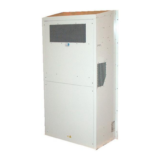
- Page 1 FC6000 No. 014952 • rev. 1.1 • 04.04.2006...
- Page 2 Der tages forbehold for trykfejl og ændringer Dantherm can accept no responsibility for possible errors and changes Irrtümer und Änderungen vorbehalten Dantherm n’assume aucune responsabilité pour erreurs et modifications éventuelles...
-
Page 3: Table Of Contents
Introduction Overview This is the service manual for the Dantherm Air Handling FC6000 unit. Introduction The table of content below gives you an overview of the main sections. Please see the complete table of content for further information about the sections. -
Page 4: Table Of Content
Table of content Introduction This is the complete table of content covering all sections in this service manual. Each main section will begin with an introduction including a separate table of content covering the exact section. Table of content This service manual covers the following topics: Topic See page Introduction... -
Page 5: General Information
Copying of this service manual, or part of it, is forbidden without prior written permission from Dantherm Air Handling. Reservations Dantherm Air Handling reserves the right to make changes and improvements to the product and the service manual at any time without prior notice or obligation. EC-Declaration of... -
Page 6: Product Description
Product description Overview This section will give you a description of the FC6000 and its functionality. Introduction Content This section covers the following topics: Topic See page General description Indicators and connections Test facility Control strategy... -
Page 7: General Description
Definitions The following terms for temperatures are used in this manual: • Ambient temperature is the outside air temperature • Return Air temperature is the temperature of the air entering the FC6000 from the electronic equipment... -
Page 8: Indicators And Connections
Indicators and connections Drawing The drawing contains numbers that corresponds to the table above. Buttons , The table contains numbers that corresponds to the drawing below: indicators and fuses Ref. Description 3 pin connector: Pin 1: Mains live, Pin 2: Unused, Pin 3: Mains neutral 2 pin connector: Pin 1: Heater live, Pin 2: Heater neutral 14 pin connector: Pin 1,2: Alarm 1 NC, Pin 3,4: Alarm 2 NC, Pin 5,6: Alarm 3 NC, Pin 7,8:... -
Page 9: Test Facility
Test facility Test function A push button – reachable from the internal side – is supplied for a quick test. This will help to identify faulty components. Once pressed, a 4 stage test is performed as described in the table below: Alarm 1-3 Step Heater... -
Page 10: Control Strategy
Control strategy Strategy This is the strategy after which the unit controls: [°C] [°C] Designation Down Designation Control temperatures are return air – warm air from the shelter. High temperature alarm High temperature alarm off Signal to start split Plit unit stop (if unit (If present) present) Internal fan max... -
Page 11: Get Ready For Use
Get ready for use Overview This section contains both a description on how to mount and how to connect the unit. Introduction Topic See page How to mount the unit How to connect the unit... -
Page 12: How To Mount The Unit
How to mount the unit Unpacking The unit is delivered in a cardboard box on a pallet. The units must be unpacked carefully and before installation the following must be checked: That the voltages on the label of the unit corresponds to the voltages available in the shelter. - Page 13 How to mount the unit, continued Mounting: louver The louver should be mounted as illustrated here. A sealing around the unit must close the gab between the wall and unit completely: NOTE! The external covers are fastened with security torx screws. A special bit is included.
-
Page 14: How To Connect The Unit
How to connect the unit Connections The unit is equipped with cables for signals, AC and DC supply, as shown below. CAUTION! The unit must be equipped with a circuit breaker. Discarding this could damage the unit. See section called “Technical information’s - Technical data” for details. Continued overleaf... - Page 15 How to connect the unit, continued Signals This scheme describes the signal cable. Colour Application White Alarm 1 - Normally Closed function: Filter clogged Brown Green Alarm 2 - Normally Closed function: Low return temperature (5 °C below heater set point) Yellow High return temperature (Higher than 39.9 °C) High ambient temperature (Higher than 39.9 °C)
-
Page 16: Service Guide
Serial numbers Product model and serial numbers are available from the nameplate, which is located on the outside of the unit. Product No.: Product name: 360012 FC6000 Contents This section covers the following topics: Topic See page Preventive maintenance Spare parts... -
Page 17: Preventive Maintenance
Preventive maintenance Introduction The air conditioner contains moving mechanical parts. Also the units are often placed in rough environments, with high temperatures, humidity and dirt. To keep the air conditioner in a shape where it will meet the specifications, preventive maintenance has to be carried out. - Page 18 Preventive maintenance, continued Tasks The following must be checked when performing the preventive maintenance visit: Item Are the fans clean and free of corrosion? Is the fan mounted securely and free of excessive vibration? Are all fan blades free of obstruction, cracks, missing blades and in balance? Do the fans rotate freely and are they free from excessive vibration or noise?
-
Page 19: Spare Parts
Spare parts Overview Introduction This section gives you a list of all available spare parts and under which number, they should be ordered. Furthermore the section contains an instruction in replacing the spare part. Contents This section contains the following topics: Topic See page Spare parts list... -
Page 20: Spare Parts List
Spare parts list Spare parts The following table concludes all spare part numbers for FC6000: Spare part Order number External filter, side 296014 External filter, front 296015 Filter 296017 296016 External controller for fan 296019 Control board 296018 Damper motor... -
Page 21: How To Replace The Filter
How to replace the filter Introduction The purpose of the filter is to ensure that dirt and humidity from the ambient air is not let through to the electronic equipment. When to replace The filter must be replaced with a maximum of 6 month interval Before you start Make sure that you have the following available before you start: •... - Page 22 How to replace the filter, continued Procedure Follow these steps to replace the filter: Step Action Switch off all power to the unit From the internal side From the internal side Unscrew the 4 safety torx 25 Unscrew the 4 torx 25 screws holding the screws holding the internal top top front cover in place and remove it cover in place and remove it...
-
Page 23: How To Replace The Frontal External Filter
How to replace the frontal external filter Introduction The purpose of the filter is to ensure that snow from the ambient air is not let through to the unit. When to replace It is not necessary to change the filter unless it is damaged Before you start Make sure that you have the following available before you start: •... - Page 24 How to replace the filter, continued Procedure Follow these steps to replace the filter: Step Action Switch off all power to the unit Unscrew the 4 safety torx 25 screws holding the internal top cover and place it on a table Remove the 2 safety torx 25 screws holding the frame containing the filter in place from the outside.
-
Page 25: How To Replace The Side External Filter
How to replace the side external filter Introduction The purpose of the filter is to ensure that snow from the ambient air is not let through to the unit. When to replace It is not necessary to change the filter unless it is damaged. Before you start Make sure that you have the following available before you start: •... - Page 26 How to replace the filter, continued Procedure Follow these steps to replace the filter: Step Action Switch off all power to the unit Unscrew the 4 safety torx 25 screws holding the internal top cover in place and remove it Remove the 4 torx 25 screws holding the frame containing the filter in place Remove the frame Replace the filter with a new one...
-
Page 27: How To Replace The Internal Fan
How to replace the internal fan Introduction The fan is placed behind the cover at the bottom of the FC6000. It can be reached from either side of the unit. It has the purpose of circulating the air inside the indoor enclosure or cool with ambient air through a filter. - Page 28 How to replace the filter, continued Procedure Follow these steps to replace the fan: Step Action Switch off all power to the unit Replacing from internal side Replacing from external side Remove the internal bottom cover Remove the external bottom cover mounted with 10 torx 25 screws.
-
Page 29: How To Replace The External Controller For The Internal Fan
How to replace the external controller for the internal fan Introduction The external controller is placed near the fan in the bottom section of the unit. It can be replaced from both sides of the unit. When to replace The external controller only needs to be replaced when it is faulty. Before you start Before you start make sure that you have the following available: •... - Page 30 How to replace the filter, continued Procedure Follow these steps to replace the extern electronic: Step Action Switch off all power to the unit Replacing from internal side Replacing from external side Remove the internal bottom cover Remove the external bottom cover mounted with 10 torx 25 screws.
-
Page 31: How To Replace The Control Board
How to replace the control board Introduction The control board is a microprocessor equipped PCB with input/outputs to all the electrical part of the FC 6000. It controls the fan based on inputs from 2 sensors placed in the unit. When to replace The control board only needs to be replaced when it is faulty. - Page 32 How to replace the filter, continued Procedure Follow these steps to replace the control board: Step Action Switch off all power to the unit Remove the right internal middle cover mounted with 4 torx 25 screws Unplug the 5 connectors and the ground connector Remove the control board by unscrewing the 6 torx 20 screws using a right- angled screwdriver Replace the control board by performing step 2 –...
-
Page 33: How To Replace The Heater Element
How to replace the heater element Introduction The purpose of the heater elements is to keep the temperature on an adequate level at low ambient temperatures. When to replace Only faulty heater elements need to be replaced. Before you start Make sure you have the following available before you start: •... - Page 34 How to replace the filter, continued Procedure Follow these steps to replace the heater element: Step Action Switch off all power to the unit Replacing from internal side Replacing from external side Remove the internal bottom cover Remove the external bottom cover mounted with 10 torx 25 screws.
-
Page 35: How To Replace The Damper Motor
How to replace the damper motor Introduction The damper motor opens and closes the damper as determined by the control board. When to replace The damper motor only needs to be replaced when it is faulty. The typical fault would be that the damper does not move at all. - Page 36 How to replace the filter, continued Procedure Follow these steps to replace the damper motor: Step Action Switch off all power to the unit Pull the Danline out from the wall Unscrew the 4 torx 25 screws that keep the internal back cover in place Loosen the two 8 mm nuts holding the damper motor fastened to the shaft for the damper Pull the damper motor up and back...
-
Page 37: How To Replace The Sensors
How to replace the sensors Introduction The 4 sensors mounted in the FC6000 unit is: • Ambient sensor • Return air sensor • Supply air sensor • Condenser sensor All the sensors are part of the cable set and are mounted without any separate connector. -
Page 38: Fault Finding Guide
Fault finding guide Introduction This section will give you an instruction in locating the fault, when the fail LED on the control panel is active. Signalling lamps The green LED illuminates as soon as the controller is powered up. The red fail LED will only illuminate in case of a detected fault. Several types of indication are shown. -
Page 39: Hotline
Hotline Introduction The After Sales Support Department of Dantherm Air Handling A/S is ready to help you in case of a problem. Information Please help yourself and us by having the following information prepared before making the call: Your name... -
Page 40: Service Agreement
Corrective and In case of malfunctions of the product Dantherm Air Handling A/S offers to do corrective emergency repair as well as emergency repair on the climate units. Agreements will be made with the customer on response time and price. -
Page 41: Technical Information
Technical information Overview Introduction This section contains the technical data for FC6000. Topic See page Technical data Dimensions Wiring diagram... -
Page 42: Technical Data
Technical data Performance This table shows the performance of the unit: Specification Unit Designation Data Load: total Heat load, int. fan, solar gain 5,88 heater Heat dissipation at nominal voltage Flow: 2200 Pressure: operating Operating pressure 70-106 Temp.: ambient °C -20 to 35 operate Noise:... -
Page 43: Dimensions
Dimensions Drawing The drawing shows the dimensions of the unit. All measurements are in millimetres. -
Page 44: Wiring Diagram
Wiring diagram Diagram The letters A and B corresponds to a scheme on the next page. Continued overleaf... - Page 45 Technical information, continued This table corresponds to the letter A on the wiring diagram. Pin number Wire colour Application Yellow Return temperature sensor White Blue Ambient temperature sensor White White Filter guard Black Damper 0V Damper direction control Black Damper +24V DC White DC fan 0V Black...
Need help?
Do you have a question about the FC6000 and is the answer not in the manual?
Questions and answers