Table of Contents

Related Manuals for DINKO Instruments D-25VT-MC


Summary of Contents for DINKO Instruments D-25VT-MC
- Page 1 VARIABLE FLOW PERISTALTIC PUMPS WITH TIMER Model D-25VT - MC Codes 1.9745.08 and 1.9745.10 MANUAL July 2023 Marked c/ Encarnació, 123 -125. Tel. +34 93 284 69 62. Fax +34 93 210 43 07 e-mail: dinter@dinko.es www.dinko.es 08024 - Barcelona...
-
Page 2: Table Of Contents
INDEX Page GENERAL INTRODUCTION ······································································ 3 PACKING LIST ······················································································· 3 RECEPTION ··························································································· 3 DESCRIPTION ························································································ 5 SPECIFICATIONS ··················································································· 9 START UP ····························································································· 9 DIGITAL TIMER ····················································································· 10 COMPLEMENTS ···················································································· 16 CHANGING THE TUBES ········································································· 18 ORDERING INFORMATION ····································································· 19 CHANGING THE FUSES ········································································· 20 TROUBLESHOOTING ·············································································... -
Page 3: 1- General Introduction
1- GENERAL INTRODUCTION Peristaltic pumps pump all kinds of liquid substances without coming into contact with mechanical elements as occurs in other pumps. They are easy to use and require minimal maintenance. The pumped substance is impelled inside an elastic tube thanks to the vacuum generated by a set of rotors that successively press and release the surface of the tube. -
Page 4: Signs/ Symbols
SIGNS/ SYMBOLS INTERPRETATION-MEANING Avoid finger contact with moving parts Danger-Risk-Caution Before opening DISCONNECT Before accessing the interior of the Pump, disconnect the the main cable power cable from the main. Before remove cover PULL OUT plug Possible overheating - Do not touch 100-230V AC 50/60Hz AC power supply voltage 110V AC 60Hz... -
Page 5: 4- Description
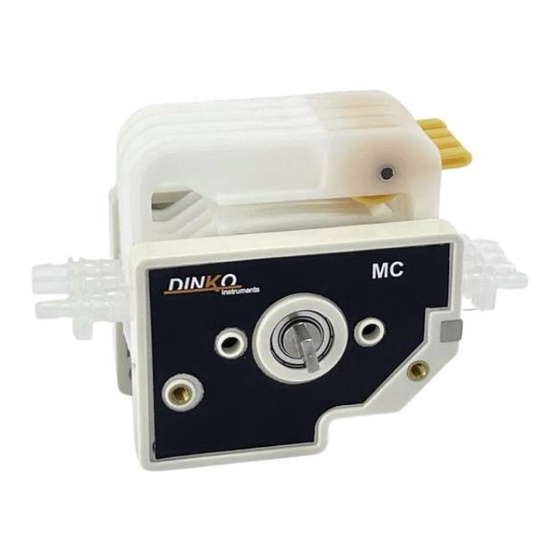
4- DESCRIPTION The D-25VT peristaltic pumps in this manual mount the 2 or 4-channel MC head that allows the tube holder cartridge to be easily removed for removal when it must be replaced due to breakage or wear. Simply press the release lever to release the cartridge from the head. Each cartridge constitutes 1 dosing channel. - Page 6 4.1.1 How to place and remove the tubes from the head. The head is delivered with the tubes in place and with the tensioner loosened. The first thing to do is adjust the tensioner so that the fluid can flow and that it is not too tight to damage the tube.
- Page 7 Now we can extract the cartridges and thus we can change the tube. We will remove the tube through the open part of the cartridge. Once outside we will put the new tube. To replace the cartridges, we will insert them into the head, first placing the left part in the guide, when we have it in the guide, we will insert the right part until it is anchored, like this with all the cartridges.
-
Page 8: Front Panel
4-2 FRONT PANEL 5 Figure a 1- Cyclic timer 2- Numerical speed control 3- Engine crank and stop selector 4- Pilot lamp 5- FULL peak flow push button 4-3 REAR PANEL Figure b 10 11 12 7- ON/OFF main switch 8- Fuse box 9- Power socket 10- Timing mode selector... -
Page 9: 5- Specifications
5- SPECIFICATIONS 5.1 DIMENSIONS Pump: 340x280x180. Weight 7Kg Operation: between 100 and 240V. 50/60 Hz. Amp.0.5 /1 5.2 FLOW TABLE - Orientative flows for each tube- D25VT Tube inner diameter mm Minimum flow: ml/min Maximum continuous flow ml/min Flows calculated with water under normal conditions without outlet back pressure. Moving the tube clamp lever to its vertical position increases the pressure of the rollers on the tube, which will require two to three times more Torque and shorten the life of the tubes. -
Page 10: 7- Digital Timer
7- TIMER When the equipment is connected, the timer starts and waits. To start it, press the ▲ key (6) 1- OUT Open/closed contact indicator-red pilot 2 - Measured time (red) 3 - Scheduled time (green) 4 -Time units (hour-minute-second) H/M/S-pilot green button. - Page 11 Menu sequence - Factory programming Pressing ▲ selects i nt Select response time 1 mS 20ms Press Pressing ▲ selects Select the menu you want use. n (N Mode ) F (F Mode) Description of the different modes in the section 7.3 Modes of use C (C Mode) r (R Mode) Press Pressing ▲...
- Page 12 7-2 Selection of operation and stop time. The timer has two programming times t.oFF and t.on indicating the status of the timer contacts. t.oFF will always be the first to count and then t.on will count . N, F modes we can only program the t.oFF , instead in the R mode , we must configure the t.oFF and he t.on .
- Page 13 Turn off the equipment and turn it on again. With the equipment turned on, press ▲ and check the programmed t.oFF time (lower green display), if it needs to be modified, see 7-2 Selection of operation and stop time (page 10). Position the direction of rotation selector in the desired position so that the head rotates clockwise or counterclockwise.
- Page 14 When you want to program a single dosage with a delay; that is, when the timer is activated, it will count the programmed time with the head stopped and at the end of said time the head will start up, it will work until the equipment stops. Programming: Timing mode selector in position I (Figure b (10)).
- Page 15 7.3.c- R mode Asymmetric cyclical mode, in which an operating time and a stop time are programmed to repeat indefinitely. This working mode is used for: When we want to carry out a repetitive dosing of a specific volume, having a stop time between dosing and dosing, to be able to place the rubber in another container to do another dosing.
-
Page 16: 8- Complements
8- ACCESSORIES 8.1 Balance for flow and dosage calibration. Reproducibility 0.1 g. 600g capacity. Code 1.9812.02 To measure the quantity dosed in the Calibration process of peristaltic pumps, it is very effective to use a precision balance with digital reading. If the liquid to be pumped has density "1"... - Page 17 CONNECTORS FOR PERISTALTIC TUBES 8.5 Reducing Connectors-Splice/Same Ends, Polypropylene For 1.6/3.2 mm internal Ø tubes. Code1.0080.15 For 3.2/4.8 mm internal Ø tubes. Code 1.0080.18 For 4.8/6.4 mm internal Ø tubes. Code 1.0080.05 For 6.4/8 mm internal Ø tubes. Code 1.0080.14 For 8/12.7mm internal Ø...
-
Page 18: 9- Changing The Tubes
9- CHANGE OF TUBES Each pump is supplied with a set of medical/food grade silicone peristaltic tubes according to FDA and USP standards, autoclavable at 120ºC, with peristaltic use range up to 80ºC and medium duration. The peristaltic quality of the tubes or rubber consists of their ability to quickly recover their roundness once the rollers of the peristaltic head of the pump have compressed it to generate the circulation of liquids inside. -
Page 19: 10- Ordering Information
9.1 AVAILABLE TUBES SILICONE Autoclavable. The most versatile tube. Platinum Cure quality silicone. Average duration. Medical/Food Grade. Excellent biocompatibility. Maximum temperature. 120ºC. Translucent. FARMED Autoclavable. Long lasting, medical/food grade. Free of plasticizers. non-toxic or hemolytic. Suitable for high pressures. Compatible with chemicals, alcohols and solvents. -
Page 20: 11- Changing The Fuses
11- CHANGE FUSES The fuse box is part of the power base located at the rear of the pump. See Figure. main switch Fuse box power base Pry with a screwdriver between the central part of the fuse holder box and the upper part of the power supply base to remove the fuse holder box. -
Page 21: 13- Maintenance - Spare Parts
Before any examination or repair of the appliance, it is necessary to disconnect the mains plug. Any initiative must be carried out by qualified personnel to avoid greater evils. Entrust your device to a technical service authorized by DINKO Instruments. The engine and its block do not require greasing, so they do not have maintenance. -
Page 22: 14- Warranty
14- WARRANTY DURATION: The warranty is established for a period of 1 year from the date of commissioning of the device, provided that the warranty card is returned to us within 8 days of said commissioning. Without this condition the warranti will not be valid. SCOPE OF WARRANTY: The guarantee is given against manufacturing and material defects for an average work week of 40 hours. -
Page 23: 15- Ec Declaration
15-EC DECLARATION OF CONFORMITY DINTER SA / DINKO Instruments c/ Encarnació, 123-125 / 08024 - Barcelona Declares that the items mentioned in the attached list, to which this declaration refers, comply with the essential safety requirements of the applicable European Directive:... - Page 24 OTHER DINKO APPARATUS - Blenders-Homogenizers - Colorimeters - Conductivity Meters - Dosing Pumps - Extractor for meat analysis - Heating Plates - Infrared Stoves - Kits for water analysis - Magnetic Stirrers - Metallic block heaters - Microscopes - Nephelometers - Orbital Shakers - Oximeters - Peristaltic Pumps...
Need help?
Do you have a question about the D-25VT-MC and is the answer not in the manual?
Questions and answers