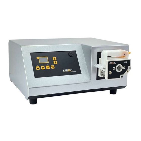
DINKO Instruments D-25Vplus Manual
Variable flow peristaltic pumps
Hide thumbs
Also See for D-25Vplus:
- Instruction manual (21 pages) ,
- Manual (18 pages) ,
- Manual (18 pages)
Table of Contents

Related Manuals for DINKO Instruments D-25Vplus


Summary of Contents for DINKO Instruments D-25Vplus
- Page 1 VARIABLE FLOW PERISTALTIC PUMPS Model D-25Vplus Codes 1.9747.08 and 1.9747.09 MANUAL July 2023 Marked c/ Encarnació, 123 -125. Tel. +34 932 846 962. Fax +34 932 104 307 e-mail: dinter@dinko.es www.dinko.es 08024 - Barcelona...
-
Page 2: Table Of Contents
INDEX Page 1- GENERAL INTRODUCTION ······················································································· 3 2- PACKING LIST ········································································································ 3 3- RECEPTION ············································································································ 4 4- DESCRIPTION ········································································································· 5 5- START UP ·············································································································10 6- CHANGING THE TUBES ··························································································14 7- ORDERING INFORMATION ······················································································15 8- MAINTENANCE – SPARE PARTS ·············································································15 9- COMPLEMENTS ·····································································································16 10- CHANGING THE FUSES ··························································································18 11- FLOW TABLE ········································································································18 12- WARRANTY ···········································································································19... -
Page 3: 1- General Introduction
Avoid using the appliance when there is the possibility of generating explosive and flammable gas mixtures. 2- PACKING LIST Description Code Quantity Peristaltic Pump D-25Vplus 1. 9747.08 or 1.9747.09 Silicone peristaltic tube 3mm Ø and connectors 1 x cartridge Power cord... -
Page 4: 3- Reception
3- RECEPTION To ensure correct reception, use of the device, and user safety, we recommend reading this manual in detail before proceeding to unpack the device and subsequent use, and especially the following points: 3.1-THE MANUAL This manual must be permanently kept within the equipment user's reach. 3.2-UNPACKING Unpack the appliance, checking that the contents match the packing list. -
Page 5: 4- Description
4- DESCRIPTION The D-25Vplus peristaltic pumps in this manual mount the 2 or 4-channel MC head that allows the tube holder cartridge to be easily removed for removal when it must be replaced due to breakage or wear. Simply press the release lever to release the cartridge from the head. - Page 6 4.1.1 How to place and remove the tubes from the head. The head is delivered with the tubes in place and with the tensioner loosened. The first thing to do is adjust the tensioner so that the fluid can flow and that it is not too tight to damage the tube.
- Page 7 Now we can extract the cartridges and thus we can change the tube. We will remove the tube through the open part of the cartridge. Once outside we will put the new tube. To replace the cartridges, we will insert them into the head, first placing the left part in the guide, when we have it in the guide, we will insert the right part until it is anchored, like this with all the cartridges.
- Page 8 4.2- DESCRIPTION OF THE FRONT PANEL (Photo a). A- Digital reader 1- Counterclockwise rotation key 2- Clockwise direction key 3- Full key 4- Start/Stop key 5- Decrease key 6- Increase key 7- Switch for programming 4.3- DESCRIPTION OF THE REAR PANEL (photo b). 1- Main ON/OFF switch 2- Fuse box 3- Power box...
- Page 9 5 PIN CONNECTOR (0-10V / 4-20 mA) nº5 (Photo b). 0-10V and 4-20 mA CONNECTION 1- Positive (+) pin for 0-10V control 2- Negative (-) pin for 0-10V control 3- Not connect 4- Positive (+) pin for 4-20 mA control 5- Negative (-) pin for 4-20 mA control WARNING : Do not use simultaneously the two inputs (0-10 V and 4-20 mA).
-
Page 10: 5- Start
5- START UP Make sure that the mains voltage is between 110 and 230 V. Connect the power cable to the rear plug and to the network. Consult the indicative flow table and install the appropriate tube. See tips in the Tube Change and Head Description section. Select the desired function. - Page 11 · Ramp mode. This working mode consists of achieving an increase or decrease in the speed of the spindle, from an initial value to a final value during a set time. If the first value is less than the final value, there will be an increase; otherwise, if the programmed initial speed is greater than the final one, there will be a decrease.
- Page 12 · Cyclic dosing mode. This work mode is used to be able to work with the pump running for a running time and stopping for a stop time, thus cyclically until we stop the equipment. Normally it is used for filling a fixed volume of several containers, having a stop time to be able to pass the end of the tube from one container to another.
- Page 13 · Pedal dosing mode. This work mode is used to be able to work with the pump running for a running time when we activate the pedal and stopping when the time reaches zero. Normally it is used for filling a fixed volume of several containers, having control by means of the pedal of when the head starts up.
-
Page 14: 6- Changing The Tubes
6- CHANGE OF TUBES Press the OFF switch. Extract the tube holder cartridge according to the indications described in the “Description” and “Head” section. When the new cartridge is installed, the tubes should be slightly taut by acting on the yellow lever. Check that the pump is OFF. -
Page 15: 7- Ordering Information
Before any examination or repair of the appliance, it is necessary to disconnect the mains plug. Any initiative must be carried out by qualified personnel to avoid greater evils. Entrust your device to a technical service authorized by DINKO Instruments. The engine and its block do not require greasing, so they do not have maintenance. -
Page 16: 9- Complements
9- ACCESSORIES 9.1 Balance for flow and dosage calibration. Reproducibility 0.1 g. 600g capacity. Code 1.9812.02 To measure the quantity dosed in the Calibration process of peristaltic pumps, it is very effective to use a precision balance with digital reading. If the liquid to be pumped has density "1"... - Page 17 CONNECTORS FOR PERISTALTIC TUBES 9.5 Reducing Connectors - Splice / Same Ends, Polypropylene For 1.6/3.2 mm ID tubes. Code1.0080.15 For 3.2/4.8 mm ID tubes. Code 1.0080.18 For 4.8/6.4 mm ID tubes. Code 1.0080.05 For 6.4/8 mm ID tubes. Code 1.0080.14 For 8/12.7mm ID tubes.
-
Page 18: 10- Changing The Fuses
10- CHANGE OF FUSES The fuse box is part of the power base located at the rear of the pump. See Figure. main switch Fuse box power base Pry with a screwdriver between the central part of the fuse holder box and the upper part of the power supply base to remove the fuse holder box. -
Page 19: 12- Warranty
12- WARRANTY 12.1 DURATION The guarantee is established for a period of 1 year from the date of commissioning of the device, provided that the warranty card is returned to us within 8 days of said commissioning. Without this condition the guarantee will not be valid. 12.2 SCOPE OF WARRANTY: The guarantee is given against manufacturing and material defects for an average work week of 40 hours. -
Page 20: 13- Ec Declaration Of Conformity
General prescriptions EN 61010-1 However, the user must observe the assembly and connection instructions indicated in the technical instructions catalogues. Name Joan A. Bravo Josep X. Sensada Position: Technical Director Responsible for Quality Signature Model: Peristaltic Pumps D-25Vplus. Codes 1. 9747.08 /1.9747.09... -
Page 21: 14- Other Appliances
OTHER DINKO APPARATUS - Blenders-Homogenizers - Colorimeters - Conductivity Meters - Dosing Pumps - Extractor for meat analysis - Heating Plates - Infrared Stoves - Kits for water analysis - Magnetic Stirrers - Metallic block heaters - Microscopes - Nephelometers - Orbital Shakers - Oximeters - Peristaltic Pumps...
Need help?
Do you have a question about the D-25Vplus and is the answer not in the manual?
Questions and answers