
Related Manuals for Panduit ATLONA OMEGA


Summary of Contents for Panduit ATLONA OMEGA
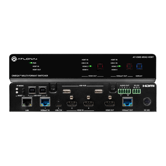
- Page 1 4K / UHD 4x2 Matrix Switcher with HDMI and HDBaseT Input Atlona Manuals AT-OME-MS42-HDBT Switchers...
-
Page 2: Version Information
Version Information Version Release Date Notes June 2024 Initial release AT-OME-MS42-HDBT... -
Page 3: Operating Notes
Sales, Marketing, and Customer Support Main Office International Headquarters Atlona Incorporated Atlona International AG 70 Daggett Drive Tödistrasse 18 San Jose, CA 95134 8002 Zürich United States Switzerland Office: +1.408.962.0515 Office: +41.43.508.4321 Sales and Customer Service Hours Monday - Friday: 6:00 a.m. - 4:30 p.m. (PST) Sales and Customer Service Hours Monday - Friday: 09:00 - 17:00 (UTC +1) https://atlona.com/... -
Page 4: Fcc Compliance
Safety and Certification 9. Do not defeat the safety purpose of a polarized CAUTION or grounding-type plug. A polarized plug has two RISK OF ELECTRIC SHOCK blades with one wider than the other. A grounding DO NOT OPEN type plug has two blades and a third grounding CAUTION: TO REDUCT THE RISK OF prong. -
Page 5: Table Of Contents
Table of Contents Introduction Features Package Contents Panel Description Front Panel Rear Panel Installation Connection Instructions Connection Diagram IP Configuration Using the Front Panel Displaying the IP Address Using the Web Server Setting the IP Address Using Commands Automatic Private IP Addressing (APIPA) Mode Device Operation LED Indicators Logging in to the Web Server... - Page 6 Table of Contents Setting the System Date and Time Setting Local Time Using an NTP Server Daylight Saving Time (DST) User Management Changing the Administrator Password Adding Users Deleting Users System Configuration Getting the MAC Address Changing the Network IP Mode Changing the Telnet Port Telnet Login Mode Adjusting Telnet Timeout...
-
Page 7: Introduction
Introduction The Atlona AT-OME-MS42-HDBT is a 4×2 matrix switcher with USB-C, HDBaseT, and HDMI inputs, plus HDMI and HDBaseT outputs. Part of the Omega™ Series of integration products for modern AV communications and collaboration, the OME-MS42-HDBT is HDCP 2.2 compliant and features HDBaseT extension for video up to 4K/60 4:2:0, plus embedded audio, control, Ethernet, and USB over distances up to 330 feet (100 meters). -
Page 8: Panel Description
Panel Description Front Panel AT-OME-MS42-HDBT HDBT IN HDBT IN USB-C IN USB-C IN HDBT IN HDMI 3 HDMI 3 HDBT OUT HDMI 4 HDMI 4 OMEGA MULTI-FOMAT SWITCHER HDMI OUT HDBaseT OUT DISPLAY IP MODE USB HUB AUDIO OUT RS-232 RX TX HDMI OUT: Input Selection RESET... -
Page 9: Rear Panel
AT-OME-MS42-HDBT HDBT IN HDBT IN Panel Description USB-C IN USB-C IN HDBT IN HDMI 3 HDMI 3 HDBT OUT HDMI 4 HDMI 4 Rear Panel OMEGA MULTI-FOMAT SWITCHER HDMI OUT HDBaseT OUT DISPLAY IP MODE USB HUB AUDIO OUT RS-232 RX TX RESET USB HOST... -
Page 10: Installation
Installation Connection Instructions 1. Connect a high-quality USB-C cable from a source to the USB-C port. 2. Connect an HDMI cable from two HDMI souces to the HDMI IN ports. 3. Connect an HDMI cable from the HDMI OUT port to a UHD/HD display. 4. -
Page 11: Connection Diagram
Installation Connection Diagram AT-CAP-SP100 AT-HDVS-CAM AT-OME-EX-TX AT-OME-MS42-HDBT Laptop Display AT-HDVS-CAM S4 2- E- M -O M AT-VTPG-1000VL Media Player M AT M UL Display AT-OME-EX-RX AT-OME-MS42-HDBT... -
Page 12: Ip Configuration
Installation IP Configuration The AT-OME-MS42-HDBT is shipped with DHCP enabled. Once connected to a network, the DHCP server (if available), will automatically assign an IP address to the unit. If the AT-OME-MS42-HDBT is unable to detect a DHCP server within 15 seconds, then the unit will use a self-assigned IP address within the range of 169.254.xxx.xxx/16. -
Page 13: Using The Web Server
Installation Using the Web Server The IP mode of the AT-OME-MS42-HDBT can also be set using the built-in web server. In order to access the web server, the IP address of the AT-OME-MS42-HDBT must be known. 1. Open the desired web browser and enter the IP address of the AT-OME-MS42-HDBT. 2. -
Page 14: Automatic Private Ip Addressing (Apipa) Mode
Installation • Setting DHCP mode 1. Connect to the AT-OME-MS42-HDBT using RS-232 or Telnet. 2. At the command line, execute the IPDHCP command using the on argument, as shown. IPDHCP on Once DHCP is enabled, the unit will be assigned an IP address by the DHCP server (if present). Automatic Private IP Addressing (APIPA) Mode If the AT-OME-MS42-HDBT is unable to detect a DHCP server within 15 seconds, when set to DHCP mode, then Automatic Private IP Addressing (APIPA) will be used to assign the an address within the IPv4 address block... -
Page 15: Device Operation
Device Operation LED Indicators The LED indicators on both the front and rear of the unit provide basic information on the current status of the AT- OME-MS42-HDBT. Description Solid green • Unit is powered using the included 24 V DC power supply. •... -
Page 16: Logging In To The Web Server
Device Operation Logging in to the Web Server Most of the AT-OME-MS42-HDBT operation is handled through the built-in web server. In order to access the web server, the IP address of the unit must be known. Refer to IP Configuration (page 12) for more information. -
Page 17: Logging In After Registration
Device Operation Logging in after Registration 1. Launch the desired web browser and enter the IP address of the AT-OME-MS42-HDBT in the address bar. 2. Enter the correct username and password in the respective fields. 3. Click the Submit button. 4. -
Page 18: Switching Modes
Device Operation Switching Modes The AT-OME-MS42-HDBT features three switching modes: Mirrored, Matrix Mode, and Matrix Mode with static route. Each of these modes will be covered in the following section. Switching modes can be configured using the built-in web server. Mirrored Mode This is the default mode. -
Page 19: Matrix Mode
Device Operation Matrix Mode This mode allows the AT-OME-MS42-HDBT to independently switch between any input to any output. Auto- switching is disabled in Matrix Mode. 1. Login to the web server. 2. Click A/V Settings in the menu bar. 3. Click the Switching Mode drop-down list and select Matrix Mode. IMPORTANT: When the AT-OME-MS42-HDBT is set to Matrix Mode, both auto-switching and display control will be disabled. - Page 20 Device Operation 5. Click the Matrix Mode HDMI Source drop-down list and select the input to be routed to the HDMI OUT port. 6. Click the Matrix Mode HDBaseT Source drop-down list and select the input to be routed to the HDBaseT OUT port.
-
Page 21: Matrix Mode W/ Static Route
Device Operation Matrix Mode w/ Static Route This mode is desirable when integrating the AT-OME-MS42-HDBT with a video conference system. In this mode, both static input and output routing are specified. Auto-Switching (page 23) must be enabled. However, the specified static input will be removed from the auto-switching pool. For example, if the HDMI IN 3 port is specified as a static input, then auto-switching will “skip”... - Page 22 Device Operation 5. Click the Matrix Mode Static Source drop-down to select the source that will be assigned as a “static” source. This source will be routed to the output selected in the Matrix Mode Static Output drop-down list. In this example, the source connected to the HDMI IN 3, will be output to the HDBaseT OUT port. The HDMI IN 3 port is the static source and the HDBaseT OUT port is the static output.
-
Page 23: Auto-Switching
Device Operation Auto-Switching The AT-OME-MS42-HDBT provides auto-switching capability, which is enabled by default. This feature will automatically switch the input to the most recently-connected source. If a source is disconnected, then the input will automatically be switched to the previously-connected source. If no sources are found, the AT-OME-MS42-HDBT will initiate a five-minute countdown timer. -
Page 24: Setting The Fallback Input
Device Operation Setting the Fallback Input The default fallback port is set to Previous. This means if multiple sources are connected, then disconnected, the AT-OME-MS42-HDBT will automatically return to last-connected port. If desired, the fallback port can be set to another input. -
Page 25: Scaler Pass-Through
Device Operation Scaler Pass-Through Click this toggle switch to enable or disable the scaler pass-through feature. When set to the ON position, 4K content will be down-scaled to 1080p. When set to the OFF position, the output resolution / timing will be the same as the input source. -
Page 26: Notes On Scaling
Device Operation 5. The Scaler toggle switch will be set to the ON state. 6. Click the toggle switch again, to return the Scaler toggle to the OFF (default) position. Notes on Scaling The following section provides important information about how the AT-OME-MS42-HDBT processes 4K (UHD) video signals. -
Page 27: Audio Management
Device Operation Audio Management The AT-OME-MS42-HDBT provides control over audio muting on HDMI OUT, HDBaseT OUT, and ANALOG OUT outputs. Audio Output Muting 1. Login to the web server. 2. Click A/V Settings in the menu bar. 3. Locate the Audio section. 4. -
Page 28: Hdcp Content
Device Operation HDCP Content Normally, if a source is transmitting HDCP content to a display that is not HDCP-compatible, then the resulting image on the display can be “snow”, image flickering, or no picture. For example, in the illustration below, a laptop source is connected to the AT-OME-MS42-HDBT. -
Page 29: Display Control
Device Operation Display Control The AT-OME-MS42-HDBT provides various methods for display control: CEC, IP, and RS-232. No external control system is required. Each of these methods will be covered in this section. IMPORTANT: The AT-OME-MS42-HDBT Switching Mode must be set to either Mirrored or Matrix Mode w/ static route. - Page 30 Device Operation 3. Login to the web server. 4. Click A/V Settings in the menu bar. 5. Verify that the Switching Mode is set to Mirrored. Display control is not supported under Matrix Mode. 6. Click Display in the menu bar. 7.
- Page 31 Device Operation 8. Under the CEC section, near the top of the page, test the power-on and power-off commands by clicking the ON and OFF buttons, respectively. The display should power-on and power-off when clicking these buttons. If the display does not respond, check the following: •...
-
Page 32: Using
Device Operation Using RS-232 1. Connect a serial cable from the RS-232 port on the AT-OME-MS42-HDBT, to the RS-232 port on the display. The included 3-pin captive screw connector should be wired as shown. AT-OME-MS42-HDBT AT-OME-MS42-HDBT HDBT IN HDBT IN HDBT IN HDBT IN To display... - Page 33 Device Operation 7. Click Display in the menu bar. 8. Click the Control Type drop-down list and select RS-232. 9. Click the RS232 Mode drop-down list and select Local RS232 Terminal. 10. Scroll down to the bottom of the page and locate the RS-232 / IP commands section. 11.
- Page 34 Device Operation NOTE: If the manufacturer is not listed in the drop-down list, then select Generic. When Generic is selected, the Products and Model drop-down lists will only list Generic. 12. Continue fine-tuning the device selection by clicking the Products and Model drop-down lists. Once all fields have been set to the proper values, the AT-OME-MS42-HDBT will populate the command fields with the proper values, based on the selected device.
-
Page 35: Using Ip
Device Operation AT-OME-MS42-HDBT AT-OME-MS42-HDBT Using IP HDBT IN HDBT IN HDBT IN HDBT IN USB-C IN USB-C IN USB-C IN USB-C IN Instead of using a serial cable to send commands, this method uses an Ethernet cable to send commands from the HDBT IN HDBT IN HDMI 3... - Page 36 Device Operation 8. Locate the TCP/IP Settings of Controlled Device section and enter the following information: 9. Scroll down to the bottom of the page and locate the RS-232 / IP commands section. 10. Click the Manufacturer drop-down list and select the manufacturer of the device that is being controlled. In the example below, Samsung is selected.
- Page 37 Device Operation have been set to the proper values, the AT-OME-MS42-HDBT will populate the command fields with the proper values, based on the selected device. 12. Some devices may require that the command be sent multiple times before an acknowledge message is sent back to the AT-OME-MS42-HDBT.
- Page 38 Device Operation HEX Command Strings a. Enter the hexadecimal command string is the correct field. An example power-on command for a display might be: \xBE\xEF\x03\x06\x00\xBA\xD2\x01\x00\x00\x60\x01\x00\x0D This command would be entered under the Set command field, under ON. Consult the documentation for the display for the correct command strings.
-
Page 39: Pass-Through Mode
Device Operation Pass-through mode In pass-through mode, RS-232 commands are sent to the AT-OME-MS42-HDBT from a control system, transmitted over HDBaseT to the receiver unit, and then to the display (sink) device. 1. Connect the RS-232 cable between the control system and the AT-OME-MS42-HDBT. 2. - Page 40 Device Operation 5. Login to the web server. 6. Click RS-232 in the menu bar. 7. Set the RS-232 settings for the display (sink) device, under the RS232 over HDBaseT Out section. These settings must match the device settings for the display. Refer to the User Manual of the display device for more information.
-
Page 41: Control Mode
Device Operation Control mode In control mode, RS-232 commands are sent from a computer or control system (DTE) to the AT-OME-MS42-HDBT (DCE). This method allows direct control of the switch for routing, IP configuration, powering-on / powering-off and other functions. IMPORTANT: Both the RS-232 port on the AT-OME-MS42-HDBT and on the control system must be set to the same baud rate, in order to communicate properly. -
Page 42: Rs-232 Control
Device Operation RS-232 Control The RS-232 port is used to directly control the AT-OME-MS42-HDBT using a control system (Console Mode) or can be used to send commands to the AT-OME-MS42-HDBT, from a control system, to the display/sink device over HDBaseT (Pass-Through Mode). Console Mode 1. -
Page 43: Pass-Through Mode
Device Operation Pass-Through Mode 1. Connect the RS-232 cable between the control system and the RS-232 port on the AT-OME-MS42-HDBT. The included 3-pin captive screw should be wired as shown. 2. Connect a category cable from the HDBaseT OUT port to a receiver (AT-OME-EX-RX). 3. -
Page 44: Display Control
Device Operation Display Control The AT-OME-MS42-HDBT provides three protocols for display control: CEC, RS-232, and IP. No external control system is required. Each of these methods will be covered in this section. IMPORTANT: The AT-OME-MS42-HDBT Switching Mode must be set to Mirrored. Display control is not supported under Matrix Mode or Matrix Mode w/ static route. - Page 45 Device Operation 6. Click Display in the menu bar. 7. Under System Settings, click the Control Type drop-down list and select CEC. This is the default control method. 8. Under the CEC section, near the top of the page, test the CEC commands for power by clicking the associated buttons.
-
Page 46: Rs-232 Configuration
Device Operation RS-232 Configuration 1. Connect a serial cable from the RS-232 port on the AT-OME-MS42-HDBT, to the RS-232 port on the display. The included 3-pin captive screw connector should be wired as shown. AT-OME-MS42-HDBT AT-OME-MS42-HDBT HDBT IN HDBT IN HDBT IN HDBT IN To display... - Page 47 Device Operation 7. Click Display in the menu bar. 8. Under System Settings, click the Control Type drop-down list and select RS-232. AT-OME-MS42-HDBT...
-
Page 48: Edid Management
Device Operation EDID Management Before a source can send picture and sound to a display device, the source reads the EDID (Extended Display Identification Data) stored in the display. The EDID contains information about what type of video and audio formats are supported by the display. -
Page 49: Edid Presets
Device Operation EDID Presets The AT-OME-MS42-HDBT provides the option of selecting a preset EDID. For information on Memory_1, Memory_2, and Memory_3 settings, refer to Storing EDID Data (page 50). IMPORTANT: If problems are encountered when using an EDID preset, try using the default setting of Connected Display. -
Page 50: Storing Edid Data
Device Operation Storing EDID Data The AT-OME-MS42-HDBT provide three memory locations which can be used to store EDID data. Any downstream EDID can be captured and stored in these locations. Each memory location is non-volatile and captured EDID data is stored after power is disconnected from the unit. 1. - Page 51 Device Operation In this example, since the display is connected to the HDMI OUT port on the AT-OME-MS42-HDBT, the HDMI Output option is selected. Here, the EDID will be stored to Memory 1. 6. Click the Save button next to the drop-down list for the memory location. 7.
- Page 52 Device Operation 8. Click any of the input drop-down list boxes. Note that the stored EDID appears as an available EDID preset for each available input on the AT-OME-MS42-HDBT. NOTE: Once an EDID is written to a memory location, it can be overwritten with a different EDID, when desired.
-
Page 53: Usb Modes
Device Operation USB Modes The AT-OME-MS42-HDBT provides three different USB modes: Follow USB, Manual, and Follow Video. Each mode provides different method of controlling USB, based on how the system is connected. All three modes will be covered in this section. Follow USB This is the default mode and functions similar to auto-switching for video. -
Page 54: Manual
Device Operation Once set to Follow USB mode, the AT-OME-MS42-HDBT will exhibit the following behavior: • If only one USB host port is connected, then the AT-OME-MS42-HDBT will use the USB host device connected to that port. • If an another USB host device is connected to the vacant USB host port, then the AT-OME-MS42-HDBT will automatically switch to that USB host device. -
Page 55: Follow Video
Device Operation Follow Video In this mode, each video input can be assigned to either USB 1 or USB 2 host ports. This mode locks the USB host device to the desired video input. Each host device will have access to the same USB devices, when video switching occurs. - Page 56 Device Operation 6. Press the HDMI OUT input selection button on the front panel and select HDMI 3. Input indicator AT-OME-MS42-HDBT HDBT IN HDBT IN USB-C IN USB-C IN HDBT IN HDMI 3 HDMI 3 HDBT OUT HDMI 4 HDMI 4 OMEGA MULTI-FOMAT SWITCHER HDMI OUT...
- Page 57 Device Operation 7. Press the HDMI OUT input selection button on the front panel and select HDMI 4. Figure 1.2 - In step 5, HDMI 4 was assigned to USB host port 2. HDMI 4 is now the active video input and Laptop 2 has access to the speaker/mic and the AT-HDVS-CAM.
-
Page 58: Setting The System Date And Time
Device Operation Setting the System Date and Time The AT-OME-MS42-HDBT uses the internal clock to store the current date and time. Time can be set using either local time or by assigning a Network Time Protocol (NTP) server. Setting Local Time 1. -
Page 59: Using An Ntp Server
Device Operation Using an NTP Server 1. Login to the web server. 2. Click Time in the menu bar. 3. Click the NTP Server field. The default NTP server is set to time.google.com. 4. Delete the contents of this field and enter the desired NTP server. 5. - Page 60 Device Operation 4. In the Start Time row, set the DST starting time by clicking the drop-down lists for month, week, day, hour, and minute. 5. Repeat the same procedure for the End Time row. 6. In the Adjust Time row, set the offset time. This time is the number of hours which Daylight Saving Time affects the local time.
-
Page 61: User Management
Device Operation User Management The AT-OME-MS42-HDBT allows the administrator password to be changed, as well as the ability to create and remove user accounts. Passwords apply to both the web server and Telnet sessions. All users have the same level of access to control the AT-OME-MS42-HDBT. -
Page 62: Adding Users
Device Operation Adding Users 1. Open the desired web browser and enter the IP address of the AT-OME-MS42-HDBT. 2. Login with the required credentials. 3. Click the Config tab. 4. Click the Add button, under the Edit column. 5. Enter the desired username and password in the Username and Password fields, respectively. 6. - Page 63 Device Operation New user 7. To login as the new user, click Logout, in the top right-hand corner of the screen, then login with the new user credentials. AT-OME-MS42-HDBT...
-
Page 64: Deleting Users
Device Operation Deleting Users 1. Open the desired web browser and enter the IP address of the AT-OME-MS42-HDBT. 2. Login with the administrator credentials. 3. Click the Remove button, next to the user to be deleted. 4. The following message box will be displayed. Click OK to confirm the deletion of the user account. Click Cancel to abort the procedure and return to the Config page. -
Page 65: System Configuration
Device Operation System Configuration The AT-OME-MS42-HDBT provides easy access to system configuration through the built-in web server, and is the recommended method to adjust network settings. Getting the MAC Address 1. Login to the web server. 2. Click System in the menu bar. 3. -
Page 66: Changing The Telnet Port
Device Operation 3. Locate the IP Mode toggle switch. The default setting of this toggle switch is DHCP. 4. Click this toggle switch to set it to STATIC IP. 5. Enter the desired IP address for the AT-OME-MS42-HDBT in the IP field. 6. -
Page 67: Telnet Login Mode
Device Operation Telnet Login Mode When a Telnet session is request, the AT-OME-MS42-HDBT provides the option to prompt for user credentials or bypass authentication before the Telnet session begins. This credentials prompt option can enabled or disabled. When prompting for user credentials, use the same login information required by the built-in web server. 1. -
Page 68: Adjusting Telnet Timeout
Device Operation Adjusting Telnet Timeout When a Telnet session is active, the AT-OME-MS42-HDBT can be set to monitor Telnet activity. If there is no activity within the specified time interval, the Telnet session will automatically be terminated, adding a measure of security. 1. -
Page 69: Setting The Host Name
Device Operation Setting the Host Name By default, the AT-OME-MS42-HDBT is assgned a hostname, which is constructed as follows: MS42HDBT-[last six digits of MAC address] For example, a default hostname might look like this: MS42HDBT-0003BC. This value can be changed to easily identify the AT-OME-MS42-HDBT within Velocity with Integrated AMS or on a network. -
Page 70: 802.1X Security
Device Operation 802.1X Security 802.1X is a server-based port authentication protocol which restricts unauthorized (rogue) clients from connecting to a Local Area Network through a public port. In its simplest form, 802.1X usually involves three parties: supplicant (client device), authenticator (Ethernet switch), and an authentication server. Before the device is permitted on the network, port communication is restricted to Extensible Authentication Protocol over LAN (EAPOL) traffic. - Page 71 Device Operation 4. Once a method is selected, the required fields for that method will be displayed. Enter the required information in each field. For the Protected EAP (PEAP) option, the fields are described as follows: • Anonymous identity Enter the identity of the authentication server in this field. EAP uses this field to identify the correct authentication server which will process the credentials.
-
Page 72: Locking / Unlocking The Front Panel
Device Operation Locking / Unlocking the Front Panel To prevent accidental pressing of the front panel buttons, the front panel buttons can be locked. This may be desirable if, for example, the AT-OME-MS42-HDBT is installed in a rack environment. By default, the front panel buttons are unlocked. -
Page 73: Resetting To Factory-Default Settings
Device Operation Resetting to Factory-Default Settings The following procedure will reset the AT-OME-MS42-HDBT to factory-default settings. The network IP mode will be set to DHCP mode. 1. Login to the web server. 2. Click System in the menu bar. 3. Click the Factory Default button. 4. -
Page 74: Configuration And Management Interfaces
Configuration and Management Interfaces Web Server The AT-OME-MS42-HDBT includes a built-in web server. Atlona recommends that the web server be used to set up the AT-OME-MS42-HDBT, as it provides intuitive management of all features. Refer to Logging in after Registration (page 17) for more information. -
Page 75: Info Page
Configuration and Management Interfaces Info Page The Info page provides various information about the AT-OME-MS42-HDBT, including software version and video information. System Info Video Info Model Name Active Input The model SKU of this product. The currently selected (active) input. Software Version Signal Type The version of firmware that the AT-OME-MS42-HDBT is... -
Page 76: A/V Settings Page
Configuration and Management Interfaces A/V Settings Page The A/V Settings page is divided into three sections: Video, Audio, and HDCP. The Video section provides controls for switching modes and input selection. The Audio section provides options to control the output audio volume and de-embedding. - Page 77 Configuration and Management Interfaces Auto Switch Three controls are available under the Auto Switch feature. NOTE: Auto-switching is only available when the Switching Mode is set to Mirrored or Matrix Mode w/ static route. The Fallback Input option is only available when the Switching Mode is set to Mirrored or Matrix Mode w/ static route.
- Page 78 Configuration and Management Interfaces HDCP Each input provides control of how HDCP content is handled. Some source devices will send HDCP content if an HDCP-compliant display (sink) is detected. However, there may be applications where sending HDCP content is not desired.
-
Page 79: Display Page
Configuration and Management Interfaces Display Page This page provides controls for CEC, device timers, and configuration for controlling external devices. NOTE: This page is not available when Switching Mode is set to Matrix Mode. Display control is disabled when matrix mode is active. CEC Command Click the ON button to send the power-on command to the display device. - Page 80 Configuration and Management Interfaces System Settings Display Auto Power Click this drop-down list to select the method of display control. The following options are available. Modes Description Active Video Presence* The AT-OME-MS42-HDBT will power-off the display if no active source is detected on the input.
- Page 81 Configuration and Management Interfaces RS-232 Page This page provides settings for both local and HDBaseT RS-232 control. RS-232 RS-232 Parameter Setting RS-232 settings for local or HDBaseT RS-232 control. • RS232 over HDBaseT In If the AT-OME-MS42-HDBT is connected to a device such as the AT-OME-EX-TX, the drop-down list boxes will be disabled and the HDBaseT baud rate will be locked at 115200.
-
Page 82: Edid Page
Configuration and Management Interfaces EDID Page This page provides controls for selecting and storing EDID data. Refer to EDID Management (page 48) for more information. EDID Settings Click these drop-down lists to select the desired EDID to be used for each input. The following EDID presets are available. -
Page 83: Usb Page
Configuration and Management Interfaces USB Page This page provides controls for setting the behavior of USB host switching. Refer to USB Modes (page 53) more information. USB Host Follow USB This is the default mode and functions similar to auto-switching for video. In this mode, the AT-OME-MS42-HDBT will detect which USB ports are connected to a host device. -
Page 84: Time Page
Configuration and Management Interfaces Time Page This page provides controls for setting the internal clock of the AT-OME-MS42-HDBT. Refer to Setting the System Date and Time (page 58) for more information. Time SNTP Configuration Simple Network Time Protocol (SNTP) is a simplified version of the Network Time Protocol (NTP), and can be used to set the time for the unit. -
Page 85: Config Page
Configuration and Management Interfaces Config Page The Config page provides management of the administrator password. The administrator username (“admin”) cannot be changed. Refer to User Management (page 61) for more information. Configuration Old Username This field cannot be changed. “admin” is the administrator user. Old Password Enter the current password for the “admin”... -
Page 86: System Page
Configuration and Management Interfaces System Page The System page is divided into two sections: Network and System. The Network section allows configuration of the IP settings of the AT-OME-MS42-HDBT. The System section provides controls for resetting the AT-OME-MS42- HDBT to factory-default settings and updating the firmware. Network MAC Address This field displays the MAC address of the AT-OME-MS42-HDBT. - Page 87 Configuration and Management Interfaces Telnet Login Mode Click this toggle switch to set the Telnet Login Mode to ON or OFF. If set to ON, then login credentials (same as web server) will be required when starting a Telnet session. Telnet Timeout Click this drop-down list to select the timeout interval, in seconds.
-
Page 88: Integration With The At-Ocs-900N
Solution Setup and Configuration Guide Integration with the AT-OCS-900N The following provides instructions on adding the AT-OCS-900N occupancy sensor as a device. The AutoSwitch feature on the AT-OME-MS42-HDBT does not need to be enabled for this to work. IMPORTANT: A username and password must be configured on the AT-OCS-900N before using the device with the AT-OME-MS42-HDBT. -
Page 89: Notes On Performing A Factory Reset On The At-Ocs-900N
Solution Setup and Configuration Guide 6. Click the Turn Display On on Occupancy toggle to enable or disable this feature. When enabled, the toggle switch will display as ENABLED and the occupancy sensor will power-on the display when the room is occupied. -
Page 90: Appendix
Appendix Updating the Firmware Using the Web Server Requirements: • AT-OME-MS42-HDBT • Firmware file • Computer on the same network as the AT-OME-MS42-HDBT 1. Download the firmware file from atlona.com and extract the contents of the .zip file to a folder on the computer desktop. - Page 91 Appendix 8. Click the OK button to begin the firmware update process. Click the Cancel button to cancel the process. 9. After the firmware update process is complete, the Login screen will be displayed. AT-OME-MS42-HDBT...
-
Page 92: Using Usb
Appendix Using USB Requirements: • AT-OME-MS42-HDBT • Firmware file • USB-A to USB-B cable 1. Download the firmware file from atlona.com and extract the contents of the .zip file to a folder on the computer desktop. 2. Power on the AT-OME-MS42-HDBT. 3. - Page 93 Appendix 6. Delete all files from the USB UPDATE drive, if any are present, then drag-and-drop the firmware file to the drive. During the firmware update process, the PWR LED indicator on the front panel of the AT-OME-MS42-HDBT will flash green. PWR LED indicator AT-OME-MS42-HDBT HDBT IN...
-
Page 94: Mounting Instructions
Appendix Mounting Instructions The AT-OME-MS42-HDBT includes two mounting brackets, which can be used to attach the unit to any flat surface. Use the two enclosure screws, on the sides of the unit to attach the mounting brackets. Single Unit Rack Installation 1. -
Page 95: Dual Unit Rack Installation
Appendix Dual Unit Rack Installation 1. Turn both units upside-down on a flat surface, next to each other, as shown. 2. Position the included mounting plate over the pre-drilled holes on the bottom of the enclosure. When attaching the mounting plate, the countersink bevels on the mounting plate should face upward. Countersink bevel F I E P L I... -
Page 96: Flat Surface
Appendix Flat Surface 1. Turn the unit upside down, on a flat surface. 2. Position the included mounting plates over the pre-drilled holes on the bottom of the enclosure. When attaching mounting plates, the countersink bevels on the mounting plates should face upward. F I E P L I D I O... -
Page 97: Specifications
Appendix Specifications Video Signal Input - HDMI, USB-C, HDBaseT Output - HDMI, HDBaseT Copy Protection 1.4 / 2.2 Pixel Clock 300 MHz UHD/HD/SD 4096x2160@60 /50/30/25/24 Hz 720p@60/59.94/50 Hz 3840×2160@60 /50/30/25/24 Hz 576p@50 Hz 1080p@60/59.9/50/30/29.97/25/ 576i@25 Hz 24/23.98 Hz 480p@60/59.96 Hz 1080i@30/29.97/25 Hz 480i@30 Hz VESA... - Page 98 Appendix Resolution / Distance 4K/UHD - Feet / Meters 1080p - Feet / Meters HDMI IN/OUT CAT5e CAT6/6a/7 Ethernet Port 1 x RJ45 Standards and Protocols HTTPS, Telnet, mDNS Speeds 10/100/1000 Mbps Addressing DHCP, Static – selectable through rear panel, IP & RS-232 commands, and built-in web server RS-232 Port...
- Page 99 Appendix Connectors HDMI IN 2 x Type A, 19-pin female HDBaseT IN 1 x RJ45, female USB-C IN 1 x USB Type-C, 24-pin female, AV input (DisplayPort Alt Mode) HDMI OUT 1 x Type A, 19-pin female HDBaseT OUT 1 x RJ45, female USB HUB 2 x Type A, 4-pin female USB HOST...
- Page 100 Appendix Footnotes (1) A maximum 120 Mbps data rate is supported over HDBaseT, due to specific USB bandwidth limitations over HDBaseT. The built-in USB hub supports USB 2.0 data rates up to 480 Mbps. (2) HDBaseT device powering and USB-C device charging are not available when the OME-MS42-HDBT is remotely powered.
- Page 101 International atlona.com 408.962.0515 41.43.508.4321 • • 35315-R1...
Need help?
Do you have a question about the ATLONA OMEGA and is the answer not in the manual?
Questions and answers