Table of Contents
Advertisement
Quick Links
INTRO |
Hey there, thanks for purchasing MKI x ES Labor! We - Erica Synths and Moritz Klein,
with help from Dr. Shalom D. Ruben, teaching professor for engineering at the University
of Colorado - have developed it as a fully-featured circuit design playground and a
powerful electronics learning tool, all in one. So no matter if you're a complete beginner
looking to get started in electronics & circuit design or a DIY synth veteran in need of a
more streamlined way to prototype your ideas - Labor has you covered.
This manual will first guide you through the assembly process, give you a rundown of the
features, and then supply you with a couple example circuits you can set up to explore
what Labor can do. In addition to this, you can also play around with those circuits in a
circuit simulator called CircuitJS. CircuitJS runs in your browser. You'll find weblinks in
the footnotes which will direct you to an instance that already has example circuits set up
for you. We strongly encourage you to fiddle with the component values and general
structure of those circuits to get a better understanding of the concepts we're laying out.
Once you're done with the basic circuits in this manual, consider investing in one of our
mki x es.edu DIY synth kits! They're compatible with your Labor and come with detailed
manuals like this one, allowing you to set up and learn about fully-fledged synthesizer
circuits like VCOs, VCFs, Sequencers and more.
Generally, this manual is intended to be read and worked through front to back, but there
were a few things we felt should go into a dedicated appendix. These are general
vignettes on electronic components, concepts and tools. Don't hesitate to check in there
whenever you think you're missing an important piece of information. Most importantly
though: have fun!
TABLE OF CONTENTS
BILL OF MATERIALS .................................................................................... 2
ASSEMBLING LABOR .................................................................................. 6
LABOR FEATURES ....................................................................................... 10
MODULAR INTERFACING SECTION CLOSE-UP ............................................. 13
EXAMPLE CIRCUITS .................................................................................... 15
USING MKI x ES DIY KITS WITH LABOR ......................................................... 28
COMPONENTS & CONCEPTS APPENDIX ...................................................... 29
1
Advertisement
Table of Contents

Related Manuals for Erica Synths MKI x ES LABOR


Summary of Contents for Erica Synths MKI x ES LABOR
-
Page 1: Table Of Contents
INTRO | Hey there, thanks for purchasing MKI x ES Labor! We – Erica Synths and Moritz Klein, with help from Dr. Shalom D. Ruben, teaching professor for engineering at the University of Colorado – have developed it as a fully-featured circuit design playground and a powerful electronics learning tool, all in one. -
Page 2: Bill Of Materials
BILL OF MATERIALS We ship Labor as a partial DIY kit. This means that while some parts of the device come pre-assembled, you’ll have to put others together yourself. Before we get started on that, let’s make sure that your kit contains all the necessary components. In the box, you should find: A couple PCBs. - Page 3 Some switches. The specific models (which you can identify by the number of connectors on their underside) are Single pole (ON – ON)/(ON – OFF) Double pole (ON – OFF – ON) A couple spacers. The specific types are 3x11mm female/female x6 3x11mm female/male 3x23mm female/male 3x23mm female/female x6...
- Page 4 If you decided to buy the full kit (instead of the basic version), your box will also include: A couple chips. Their specific models (which are printed onto their bodies) are TL072 (dual op amp) TL074 (quad op amp) 40106 (hex schmitt trigger inverter) 4017 (decade counter) 4015 (dual shift register) A couple of transistors.
- Page 5 A bunch of capacitors. The specific values (which may be encoded and printed onto their bodies) are 1µF 470nF 100nF 10nF 2.2nF Some diodes. The specific model names (which are printed onto their bodies) are 1N4148 (signal) A couple more LEDs (light emitting diodes). The specific model (which you can identify by measuring their body’s width) 3mm (red)
-
Page 6: Assembling Labor
ASSEMBLING To help you locate the various parts we need during the assembly process, here’s what they look like. Main PCB Plywood base Expansion Slot Panel Utility Section Panel Breadboard Panel Modular Interfacing Section Panel Adapter PCB Adapter PCB... - Page 7 To get going, you’ll need both a soldering iron/station, a screwdriver and some pliers. Start by soldering the black female 4-pin headers to the modular interfacing section at the bottom of the main PCB. There are 32 headers in that section. Start by soldering one pin of each header and make sure it is properly aligned with the PCB’s silkscreen, then solder the remaining 3 pins.
- Page 8 Now, use the male/female spacers to attach the main PCB to the plywood base. The shorter spacers are for the top corners, while the longer ones are for the bottom. Next, we need to add the utility section panel. For that, make sure that there are no nuts on the jack sockets in the top right corner, and only one nut on each of the switches.
- Page 9 Next, continue with the jack sockets and switches. Again, follow the silkscreen on the small PCBs and solder the components in place. Next, cut the 40-pin male connectors into sections of 4 connectors using your pliers and solder two each onto the bottom of the adapter PCBs. Make sure the connectors are aligned with the silkscreen and that they are perpendicular (90 degrees) against the PCB.
-
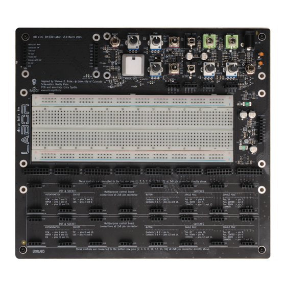
Page 10: Labor Features
FEATURES Labor comes equipped with everything you need for prototyping your circuits. In the center, there’s a standard 830 tie point breadboard. This is where you’ll insert your non- interfacing components like resistors, capacitors, diodes, and ICs. Right next to the breadboard, you’ll find a power header. - Page 11 status indicator LEDs will stay dark even after you flip the power switch. If that happens, immediately remove the power plug from the device, check your circuit and fix the short. (People often accidentally mix up the positive and negative supply rail connections on a chip – this also creates a de-facto short circuit.) Be sure to always turn your device off...
- Page 12 Like the oscillator, the gate/trigger/envelope generator has two types of output: one jack socket labeled EG OUT for driving external gear, and a header labeled EG OUT for connecting the generator to your breadboarded circuit. Next to the generator, there’s a buffered variable CV source. It can produce any voltage between -8 V and 8 V, and it’s controlled via the knob labeled CV SOURCE.
-
Page 13: Modular Interfacing Section Close-Up
MODULAR INTERFACING SECTION CLOSE-UP Before you can insert your potentiometers, sockets and switches into Labor’s modular interfacing section, you’ll first need to solder them to the included adapter mini-PCBs. (This is described in detail in the assembly guide section above.) Afterwards, they should look something like this. - Page 14 Knowing this, we can work out which pin connects where for our pot & socket – see the illustration on the left. Any pins marked with an X are inactive and don’t connect anywhere. Note that the jack socket is automatically hooked up to the ground rail – ...
-
Page 15: Example Circuits
EXAMPLE CIRCUITS: LOW PASS FILTER To do a first test with your Labor, let’s set up a simple passive low pass filter. All we need for this are two components: a potentiometer and a capacitor. If we arrange them like this, any signal we feed into the input on the left will have its overtones removed to varying degrees, depending on the amount of resistance we dial in. - Page 16 But note that „full“ in this context simply means as full as the given pressure can force it to be. If we were now to increase the pressure, the balloon would fill up even more – until the forces are balanced again. Of course we can’t do this indefinitely.
- Page 17 the maximum voltage level, and the voltage inside the capacitor gets weaker as it empties out. The end result is a waveform that is decidedly less angular than the square wave we sent in. Because of this, we can expect it to sound a lot less harsh. To try this for yourself, here’s how you could set it up.
- Page 18 all the way to the left. You should hear a bright, buzzing sound. Now slowly turn the pot in the other direction. The sound should gradually get less bright. This is because the high frequency content gets filtered out as the resistance increases. You’ll notice that you cannot fully close the filter.
- Page 19 EXAMPLE CIRCUITS: OSCILLATOR Next, let’s try setting up a simple square wave oscillator ourselves. For this, we need three components: a schmitt trigger inverter, a resistor, and a capacitor. In case you don’t know what a schmitt trigger inverter does: you can think of it as two separate things.
- Page 20 At some point, the voltage above the capacitor will cross the schmitt trigger inverter’s upper input threshold, causing it to latch into the high input state. In response, it’ll put its output into the low state. Because the capacitor voltage is now much higher than the inverter’s output voltage, current will flow out of the cap and back into the output.
- Page 21 To try this out, here’s how you could set it up. First, we plug a 40106 hex schmitt trigger inverter chip (which contains six individual schmitt trigger inverters) into the breadboard and connect it to +12 V and ground. Then, we add a 100 nF capacitor at one schmitt trigger inverter’s input.
- Page 22 EXAMPLE CIRCUITS: CRUDE VCA Next, let’s set up a circuit that allows us to test your Labor’s envelope generator: a simple, crude VCA (Voltage Controlled Amplifier). For this, we need five components: a transistor, two resistors, a capacitor and a diode. To understand how it works, let’s take this circuit apart.
- Page 23 Alright, but what about the diode between the 33k resistor and the collector? Well, there’s one small issue with this setup. If the control voltage is 0 and there is no diode there, current will flow into the base, out of the collector and towards that low voltage node.
- Page 24 EXAMPLE CIRCUITS: BRIDGED-T OSCILLATOR Finally, let’s set up a circuit that allows us to test Labor’s trigger generator: a bridged-t oscillator. It consists of just one op amp, two resistors and two capacitors. Together, they form a strange sine wave oscillator that needs to be kickstarted by a voltage pulse to actually oscillate.
- Page 25 But because there is a resistor to ground between the two caps, we’ll see current drain out from the first capacitor. Which means that the voltage applied to the second cap (and subsequently, the inverting input) will drop. To compensate, the op amp will raise its output voltage.
- Page 26 Eventually, we’ll again reach a tipping point where the whole mechanism reverses. Only this time, it’ll be at a slightly lower output voltage. That’s because with every charging and discharging cycle, we lose a bit of the momentum we initially put in. The circuit behaves kind of like a pendulum that way.
- Page 27 To try this out, here’s how you could set it up. First, we’ll set up a TL072 chip, which houses two generic op amps, and connect it to the positive and negative rail. Next, grab Labor’s trigger from the header labeled EG OUT and connect it to the top op amp’s non-inverting input via a 100k/10k voltage divider.
-
Page 28: Using Mki X Es Diy Kits With Labor
USING OUR DIY KITS WITH In the manuals for our MKI x ES.EDU DIY kits, you’ll find suggested breadboard layouts at the end of most chapters. You can replicate them as-is on your Labor, but to get the most out of it, we recommend that you handle the interfacing elements like jack sockets, potentiometers and switches via Labor’s modular interfacing section instead. -
Page 29: Components & Concepts Appendix
COMPONENTS & CONCEPTS APPENDIX In this section, we’ll take a closer look at the components and elemental circuit design concepts we’re using to design our circuits. Check these whenever the main manual moves a bit too fast for you! THE BASICS: RESISTANCE, VOLTAGE, CURRENT There are three main properties we’re interested in when talking about electronic circuits: resistance, voltage and current. - Page 30 RESISTORS While a conductive wire is like a very big pipe where lots of water can pass through, a resistor is like a narrow pipe that restricts the amount of water that can flow. The narrowness of that pipe is equivalent to the resistance value, measured in ohms (Ω). The higher that value, the tighter the pipe.
- Page 31 CAPACITORS A capacitor is a bit like a balloon that you can attach to the open end of a pipe. If there’s some pressure in the pipe, the balloon will fill up with water until the pressure equalizes. (Since the balloon needs some space to expand into, both of the capacitor’s legs need to be connected to points in your circuit.) Then, should the pressure in the pipe drop, the balloon releases the water it stored into the pipe.
- Page 32 DIODES Diodes are basically like one-way valves. Current can only pass through in one direction – from anode to cathode. That direction is indicated by the arrow in the diode symbol and by a black stripe on the diode’s casing. So any current trying to move in the opposite direction is blocked from flowing.
-
Page 33: Voltage Dividers
VOLTAGE DIVIDERS A voltage divider is really just two resistors set up like this: input on the left, output on the right. If R1 and R2 are of the same value, the output voltage will be half of what the input voltage is. How does it work? Let’s use our analogy again: so we have a pipe on the left, where water is being pushed to the right with a specific amount of force. - Page 34 POTENTIOMETERS Potentiometers can be used as variable resistors that you control by turning a knob. But, and that’s the handy part, they can also be set up as variable voltage dividers. To see how that works, let’s imagine we open one up. Inside, we would find two things: a round track of resistive material with connectors on both ends plus what’s called a wiper.
- Page 35 AC COUPLING What is AC coupling – and how does it work? Imagine two adjacent pipes with a balloon between them. Now, no water can get from one pipe into the other, since it’s blocked by the balloon. But, and that’s the kicker, water from one side can still push into the other by bending and stretching the balloon, causing a flow by displacement.
- Page 36 OP AMPS Op amps might seem intimidating at first, but they’re actually quite easy to understand and use. The basic concept is this: every op amp has two inputs and one output. Think of those inputs like voltage sensors. You can attach them to any point in your circuit and they will detect the voltage there without interfering.
- Page 37 OP AMP BUFFERS/AMPLIFIERS Buffering, in the world of electronics, means that we provide a perfect copy of a voltage without interfering with that voltage in the process. With an op amp-based buffer, the buffering process itself works like this. We use the non-inverting input to probe a voltage, while the inverting input connects straight to the op amp’s output.
- Page 38 amplifier because the output signal is in phase with the input. For an inverting buffer/amplifier, the input signal is no longer applied to the non-inverting input. Instead, that input is tied directly to ground. So it’ll just sit at 0 V the entire time.
- Page 39 BIPOLAR JUNCTION TRANSISTORS Bipolar junction transistors (or BJTs for short) come in two flavors: NPN and PNP. This refers to how the device is built internally and how it’ll behave in a circuit. Apart from that, they look pretty much identical: a small black half-cylinder with three legs. Let’s take a look at the more commonly used NPN variant first.
- Page 40 collector current. (At least not without some unwanted side effects.) Third, also unlike a resistor, a BJT is not a linear device. Meaning that a change in collector voltage will not affect the collector current. And fourth, the collector current is affected by the transistor’s temperature! The more it heats up, the more current will flow.
Need help?
Do you have a question about the MKI x ES LABOR and is the answer not in the manual?
Questions and answers