
Related Manuals for Harvard Bioscience BIOCHROM BIO 30+ Series


Summary of Contents for Harvard Bioscience BIOCHROM BIO 30+ Series
- Page 1 BIOCHROM BIO 30+ AMINO ACID ANALYSER USER MANUAL PLEASE READ THIS MANUAL CAREFULLY BEFORE USING THE BIO 30+ SERIES AMINO ACID ANALYSER. 5061-058-REV-12 – JAN 2023...
- Page 2 Description of Version Changes Date Version # List of changes 01/03/2010 • Initial version 17/08/2011 • Part number for finger tight fittings changed from 80-2104-45 to 80-6002-13 to reflect the use of the new high-pressure fittings. • Section 4.6.4: BAM software description and operations improved.
- Page 3 • Updated section 6.2.1 to give reference of Reagent IFU. • Updated sections 8.2.1, 8.2.2, 8.2.5,and 8.2.6 to add part no. for products Ultrosolve Plus and Ultra Ninhydrin solution. • Updated reference in section 8.2.10 from ‘ISO Guide 34’ to ‘ISO 17034’. •...
- Page 4 General Index BIO 30+ PART NUMBER, WARRANTY AND LIABILITY SAFETY AND REGULATION Describes the basic principles the Bio 30+ Series uses and includes a detailed instrument specification and health and safety information. FUNCTIONAL DESCRIPTION Explanation of the fluidics system and the control system and how they inter- relate FLUIDICS SYSTEM Detailed description of the components and how they operate within the...
- Page 5 0 Bio 30+ Part Numbers, Warranty and Liability. Part Number & Description Part Number Description Bio 30+ System Physio Accel 80-6000-50 Bio 30+ Physio Accelerated 80-6000-51 Bio 30+ Physio Accel W/O A/S 80-6000-52 Bio 30+ System Physio HP 80-6000-53 Bio 30+ Sys Physio HP EZ Nin 80-6000-53EZ Bio 30+ Physio High Performance 80-6000-54...
-
Page 6: Warranty And Liability
Warranty and Liability Biochrom Ltd guarantee that the product supplied has been thoroughly tested to ensure that it meets its published specification. This warranty may only be valid if the product has been used within its specification and in all respects has been operated and maintained in a normal, proper manner in accordance with the Instruction Manual. - Page 7 Pictorials used in this manual The following pictorials are used in this guide: The danger sign warns about a hazard. It calls attention to a procedure or practice which, if not adhered to, could result in injury or loss of life. Do not proceed beyond a danger sign until the indicated conditions are fully understood and met.
- Page 8 Abbreviation of Terms Terms Abbreviation Globally Harmonized System PTFE Polytetrafluoroethylene PEEK Polyether Ether Ketone Polyvinyl Chloride Coefficient of Variation Relative Standard Deviation Phenylketonuria Phenylalanine Tyrosine High Performance High Resolution Sulphosalicylic Acid EDTA Ethylenediaminetetraacetic Acid HPLC High-Performance Liquid Chromatography Hydrochloric Acid Isopropyl Alcohol/Isopropanol European Research Network for Evaluation and ERNDIM...
-
Page 9: Table Of Contents
SAFETY AND REGULATION CONTENTS Safety And Regulation ....................1.2 1.1 Intended Use ....................1.2 1.2 Technical Specification ................1.2 1.3 Analytical Performance Characteristics ............ 1.4 1.4 Clinical Performance Characteristics ............1.5 1.5 Manufacturer’s Details .................. 1.5 1.6 Authorised Representative................1.6 1.7 Electrical Safety .................... -
Page 10: Intended Use
1 SAFETY AND REGULATION 1.1 Intended Use The Biochrom Bio 30+ Amino Acid Analyser is a fully automated laboratory instrument intended as an aid to the diagnosis of phenylketonuria by trained professionals. The Biochrom Bio 30+ Amino Acid Analyser is designed to provide quantitative analysis of phenylalanine and tyrosine present in physiological samples using ion-exchange chromatography in combination with post-column derivatization using ninhydrin. - Page 11 Ninhydrin Stored under nitrogen pressure in a 2.0 litre graduated plastic-coated glass bottle. Pumps Two independently controllable pumps with integrated pressure transducer. Ceramic pump head, sapphire pistons and valves, adjustable flow rate and time controlled automatic piston flush. Operating Buffer pressure: maximum 145 bar (minimum 15 bars). Ninhydrin Pressures pressure: maximum 24 bar (minimum 6 bars).
-
Page 12: Analytical Performance Characteristics
•Mouse, Keyboard & Monitor •Windows 7 Professional 64-bit. •Microsoft .NET framework v3.5 or higher Interference Unidentified substances. and Cross- In both normal and diseased clinical samples there have always been reactivity substances that have never been identified. These are minor peaks and generally do not interfere with the detection of major metabolites. -
Page 13: Clinical Performance Characteristics
• Lithium Accelerated analysis: Maximum time to the Arginine peak is 110 min • Lithium High Performance analysis: Less than 172 min injection to injection • Lithium High Resolution analysis: Less than 265 min injection to injection Limits of Detection: For selected amino acids the lower detection limit is not less than 15 picomoles. -
Page 14: Authorised Representative
Biochrom Limited Unit 7, Enterprise Zone 3970 Cambridge Research Park Beach Drive, Waterbeach Cambridge, United Kingdom, CB25 9PE E-mail : support@biochrom.co.uk Tel: +44 (0)1223 423723 1.6 European Authorised Representative Medical Device Safety Service GmbH (MDSS) Schiffgraben 41, Hannover 30175 Germany 1.7 Electrical Safety The instrument’s electrical system is built to very high safety standards. -
Page 15: Installation Requirement
Fig. 1.2 Mains Switch Panel 1.8 Installation Requirement The Bio 30+ comprises three modules: • Fluidics cabinet Autosampler unit • Computer and monitor • When assembled, the Bio 30+ requires bench space of approximately 180 cm wide by 70 cm deep, including the computer. -
Page 16: Environmental Consideration
1.8.1 Environmental Consideration Required Services Oxygen free nitrogen gas (99.99%), regulated to 5 bar. Drainage facility. Ambient Operating 15°C to 25°C Temperature Maximum Humidity 80% at 25°C 1.8.2 Special Considerations The amino acid analyser must be used under analytical laboratory conditions with additional environmental considerations. -
Page 17: Chemicals Hazard
This sign is located on hot surfaces such as the reaction coil, the lamp cover and the column oven. Hot surface 1.11 Chemicals Hazard The Bio 30+ is designed to enable amino acid analyses to be performed safely and consistently. However, the chemicals used in amino acid analysis must be handled with care. Specific chemical warnings are given below: Product # Description... -
Page 18: Device And Waste Disposal
If any chemical is swallowed, seek medical advice immediately and show the container or label. Please also refer to the Material Safety Data Sheets produced for each chemical. These can be accessed via http://www.biochrom.co.uk/msdssearch.asp 1.12 Device and Waste Disposal The waste container must be located below the level of the instrument. It should be labelled according to local regulations. - Page 19 From the reaction coil, the eluate/ninhydrin mixture is fed to the photometer unit where the amount of each coloured compound is determined by measuring the amount of light absorbed. The light absorption is measured at two wavelengths, 570nm and 440nm. This is because secondary amines such as Proline and Hydroxyproline produce coloured compounds which absorb light with a wavelength of 440nm, whereas other amino acid coloured compounds absorb light at 570nm.
-
Page 20: Functional Description
FUNCTIONAL DESCRIPTION CONTENTS FUNCTIONAL DESCRIPTION ................ 2.2 2.1 Introduction ....................2.2 2.2 Control System ....................2.2 2.3 Fluidics System ....................2.4 2.3.1 Buffer Supply ......................2.4 2.3.2 Ninhydrin Supply ....................2.4 2.3.3 Reaction Coil ......................2.4 2.4 Nitrogen Supply ..................... 2.5 2.5 Use Of Buffer System .................. -
Page 21: Introduction
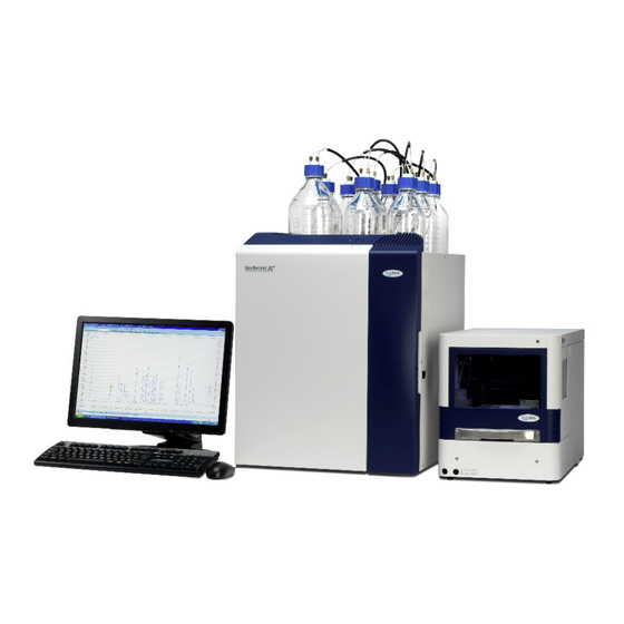
2 FUNCTIONAL DESCRIPTION 2.1 Introduction This section describes the control system and the fluidic system used in the Bio 30+ Amino Acid Analyser. 2.2 Control System The control system is as shown in Fig 2.1. Five buffer solutions and the regeneration solution are fed via six solenoid valves to the buffer pump. - Page 22 Chemicals bottles Analytical column Reaction coil and photometer tray Pumps Autosampler tray Figure 2.2 Bio 30+ general description The temperature of the analytical column is regulated by two Peltier units controlled by the electronic system. When the sample has been loaded onto the column, the buffer solenoid valves are energised sequentially to deliver a series of successively higher pH buffer solutions.
-
Page 23: Fluidics System
2.3 Fluidics System 2.3.1 Buffer Supply The buffer storage area contains six bottles for buffers, the ninhydrin reagent and two extra bottles, one for the coil flush device, the other for the piston flush system. The bottles are supplied with low pressure nitrogen from the regulated nitrogen supply. A pressure regulator valve is used to decrease the main nitrogen pressure from 5 bar to the low pressure required by the bottles. -
Page 24: Nitrogen Supply
2.4 Nitrogen Supply The nitrogen supply from the cylinder is regulated to 5 bar at the cylinder and fed to the instrument. At a pressure of 5 bar, the nitrogen is used to operate the coil flush device. A pressure regulator valve produces 0.1 to 0.2 bar of gas for delivery to the buffer bottles, the coil flush bottle and the ninhydrin reagent bottle. - Page 25 FLUIDICS SYSTEMS CONTENTS FLUIDICS SYSTEM ..................3.2 3.1 Introduction ....................3.2 3.2 Buffer Storage Area ..................3.2 3.3 Ninhydrin Reservoir ..................3.2 3.4 Autosampler ....................3.2 3.4.1 General description ....................3.2 3.4.2 Injection modes ..................... 3.3 3.5 Analytical Column ..................3.4 3.6 Pump Assembly ....................
-
Page 26: Fluidics System
3 FLUIDICS SYSTEM 3.1 Introduction This section describes in detail the individual modules that comprise the fluidics system of the Bio 30+. To facilitate this, the instrument is divided into seven major areas and the modules in these areas described individually. 3.2 Buffer Storage Area The buffer storage area is at the top of the fluidics cabinet, holding eight 1 litre graduated plastic coated glass bottles. -
Page 27: Injection Modes
Fig 3.1 Biochrom Alias Autosampler 3.4.2 Injection Modes To enable a series of analyses to be performed without operator intervention, the samples are introduced into the analytical system using the sample loop. 3 injection modes are available: Flushed loop, partial loop and microlitre pickup. Partial mode: A minimum of 1µl to a maximum of 100µl of sample may be loaded •... -
Page 28: Analytical Column
3.5 Analytical Column The analytical column is mounted vertically on the front of the instrument, as shown below. This high pressure, PEEK column is supplied as required for your individual analytical requirements. Cation exchange resin is packed into the column. The resin is retained within the column by PEEK frits. -
Page 29: Pump Assembly
3.6 Pump Assembly 3.6.1 Dual Piston Pumps The Bio 30+ is equipped with a high pressure, low volume pump unit which comprises two Knauer Azura P4.1S pumps. One pump provides the buffer supply, the other supplies ninhydrin. The flow rate of each pump is controlled via the operating software, these flow rates being set as required for the particular application. -
Page 30: Automatic Piston Wash System
3.6.3 Automatic Piston Wash System The pumps have an automatic piston flushing system attached which constantly flushes the back of the pistons with deionised water to prevent any build up of salts. The automatic piston flushing system is controlled via a solenoid valve mounted on the left hand side of the fluidic cabinet. -
Page 31: Pre-Wash Column
3.7.1 Pre-wash Column The PEEK pre-wash column is mounted on the front of the instrument below the analytical column and is connected on the outlet (high pressure) side of the buffer pump. Ammonia present in all buffers is retained by the pre-wash column and thus prevented from being fed to the analytical column. -
Page 32: Mixing Manifold
3.8.2 Mixing Manifold The mixing manifold is a specialised T connection into which are fed the eluate from the analytical column and the ninhydrin reagent. This mixture is then fed to the reaction coil. 3.8.3 Back Pressure Valve A back pressure valve is connected to the photometer outlet and maintains the liquid in the reaction coil under pressure. -
Page 33: Instrument Controls
INSTRUMENT CONTROLS CONTENTS INSTRUMENT CONTROLS................4.2 4.1 Overview Of System Operation ..............4.2 4.1.1 BioSys Control and Data Handling ................4.2 4.1.2 Running BioSys Setup ..................... 4.3 4.2 Alias Manager Software Operations ............. 4.9 4.2.1 Operation tab ......................4.9 4.2.2 Settings tab ......................4.10 4.2.3 Service mode tab .................... -
Page 34: Overview Of System Operation
4 INSTRUMENT CONTROLS When a complete system has been ordered, the instrument is supplied with a computer. In this instance, the complete system will have been set up and tested at Biochrom and should be ready to use after installation. However, if the computer was obtained locally, then the software will need to be installed and set up. -
Page 35: Running Biosys Setup
A special link enables the interfacing of BioSys and the OpenLAB data handling package. This link allows BioSys to automatically open an OpenLAB method and starting data collection upon an injection step in the instrument program. 4.1.2 Running BioSys Setup The Setup window •... - Page 36 Click on the Autosampler tab and select a proper communications port (default is COM 7). This COM port must match the Biosys Virtual Port set in the Alias Manager (see section 4.6.2.2). Set the the Autosampler type to Midas+Alias. The Id No. should be set to 60. A different loop volume can be set if the default loop of 200µL is replaced.
- Page 37 To enable the OpenLAB-BioSys link, click on the button next to the blank box and select the Bio 30+ instrument from the list. Set the Method, Data and Sequence paths by clicking on the buttons for each path. Note: BioSys will be able to start the integration system every time a programmed injection takes place.
- Page 38 These settings tell the Control program where the sample lists, the programs and the main program directory are saved in the computer hard drive. 5061-058-REV-12 – 05 JAN 2023 Section 4...
- Page 39 o Default parameters The buffer and ninhydrin pump flow rates and the reaction coil default temperature can be set here. o Report Options The Sample and Run reports can be enabled here so that they are printed at the end of a sample list. The print option can be disabled if required. 5061-058-REV-12 –...
- Page 40 o System Print Details The header for the printed programs can be customised here. 5061-058-REV-12 – 05 JAN 2023 Section 4...
-
Page 41: Operation Tab
4.2 Alias Manager Software Description 4.2.1 Operation tab Information bar Tray control: Click on Front to move the sample tray forward. This allows the access to the • samples and enables the removal of the tray from the compartment. Click on Home in order to move the tray back in its default position •... -
Page 42: Settings Tab
4.2.2 Settings tab Needle height: • Range: Select the distance in mm between the bottom of the vial and the needle. Click apply to record the change. • Needle Exchange: click on this button to position the needle in the exchange position. Needle Home: Once the needle has been changed, click on this button to reinitialise •... -
Page 43: Service Mode Tab
4.2.3 Service mode tab This tab is only accessible for service engineers with a suitable password. 4.2.4 About tab This tab shows the instrument type, serial number and software version details. 5061-058-REV-12 – 05 JAN 2023 4.11 Section 4... -
Page 44: Minimized Window
4.2.5 Minimized window This window is triggered when the minimize button is clicked on the main Alias Manager window. It contains all the basic information along with main operations buttons. To recover the full window of the Alias Manager, click on Maximize. 5061-058-REV-12 –... -
Page 45: The Manual Operation Window
4.3 Biosys Control Software Description The BioSys program consists of five main modules, these are accessed either via the following path: Start\All Programs\Biochrom\BioSys or by clicking on the View menu in any of the BioSys windows. BioSys Manual: This is the module where the instrument can be operated manually, to check flow rates, temperatures, pressures, etc. - Page 46 Click on the Recorder checkbox to start the paper drive, this is only valid for recorders that have a remote paper drive control. Click on the Override checkbox to bypass the error detection system. This allows access to operate the instrument in case a non fatal fault has shut it down. Note: do not run the instrument with the override on.
-
Page 47: The Biosys Programmer Window
Control\Assign Buffers… This command opens a dialogue window where the buffers and the ninhydrin batch numbers can be entered. This table can be printed on a program header if required. Control\Autosampler… Similar function to the Sample Load button. Control/Reagent Management… This command opens a dialogue window where the volume of the buffers and reagent can be entered. - Page 48 The Elite button in the Sample Details window opens another dialogue window where a data collection method can be set for each sample in the list. The Data directory and the data filenames can also be set here. A completed Sample List would look like this: The Go to Step button can be used to go to a selected sample later in the list, it can also be used to run the Sample List from a selected sample.
- Page 49 Column display: Right-click on the Sample List window and select Columns from the menu. The Columns command is used to customise the sample list layout. Columns can be added by highlighting them in the Available Titles box and using the arrow to move them to the Current Titles box.
- Page 50 4.3.2.1 Running the Sample List The sample list is started by clicking on the Run button. If OpenLAB security is enabled, a dialogue window opens to enter the name and password required to access OpenLAB. Click on the Program tab to see the current program steps and details. Completed steps are indicated by a tick mark on the left hand side of the window and the current step by a green arrow.
-
Page 51: The Biosys Editor Window
4.3.3 The BioSys Editor Window The BioSys Editor is required to create and edit the programs required by the BioSys Programmer. The Program defines a sequence of steps that perform an injection, an analysis and the column regeneration. A Sample List is a list of samples to be run, each of which consists of a program and associated sample details. - Page 52 4.3.3.1 The Program Editor The Program Editor is used to create and edit programs. New programs are created by clicking on New from the Main Menu. The choice of creating a Program or a Sample List is given. Please select Program. A default program can also be opened by clicking on Open and by selecting a default program located in the Standards folder.
- Page 53 Delete The currently selected step, or steps, are deleted. The currently selected step, or steps, are copied to the clipboard before being deleted. Copy The currently selected step, or steps, are copied to the clipboard. Paste Any steps currently stored in the clipboard are pasted into the Program List at the current cursor position.
- Page 54 4.3.3.2 The Sample List Editor The Program Editor can also be used to create or edit Sample Lists. New sample lists are created by clicking on New from the Main Menu. The choice of creating a Program or a Sample List is given. Please select List. Click on the End line on the Sample List window, this action enables the Insert command in the Edit menu and the Insert, Remove and the Edit buttons on the button ribbon.
-
Page 55: The Biosys Fluidics Window
4.3.4 The BioSys Fluidics Window This application enables the operator to view all system functions during operation in a convenient layout and gives a quick overview of system status. Before start up the fluidics screen shows the main system components and the way in which they are connected in the analyser. - Page 56 4.3.4.1 System status information Various types of information are provided by the fluidics window icons depending on the components they represent. The icons listed below represent components that have no function other than representing a physical component in the instrument. These have no controllable features and no displayable states and are included only to show their location in the fluidics system.
- Page 57 The Autosampler control This represents the Autosampler. This has options to start a Load sequence after setting the Load parameters. The autosampler icon will be animated when an injection is taking place. The Column This is associated with a temperature gauge that displays the current temperature. The heating bars of the column will be shown as red when heating, blue when cooling and grey at temperature.
- Page 58 4.3.4.2 Analyser operation from the menus The BioSys Fluidics window also contains a menu structure, which allow access to other features and applications. The various options available under each menu are given below. File/Setup Opens the BioSys Setup application File/Shutdown This will shut the instrument down and close all BioSys applications.
- Page 59 Control/Optical/Lamp This switches the photometer lamp on or off Control/Optical/Recorder This switches the Recorder on or off Control/Optical/Baseline/440… or 570… This sets the selected channels baseline position Control/Optical/Optical Density/440… or 570… This sets the selected channels O.D setting for the recorder output Control/System/Override This toggles the Override parameter.
-
Page 60: The Biosys Utilities
4.3.5 The BioSys Utilities These are accessed by clicking on the arrow in the task bar and by right clicking on any of the two icons on the task bar. Commander BioSys 1000 4.3.5.1 The BioSys Commander The BioSys Commander has a simple menu, selected by right-clicking on the icon in the task bar showing Display Commander, Display Traces and Help. - Page 61 4.3.5.2 The BioSys 1000 Controller The current status of the instrument and the autosampler can be displayed from the BioSys 1000 Controller. Simply right click on the BioSys 1000 icon in the task bar and select Display status The window shows the entire instrument status. It is divided into a number of tabs: Setup, Autosampler, Errors, Diagnostics, System, Control and Reagent Management.
-
Page 62: Automatic Operation
4.4 Automatic Operation 4.4.1 Operating the BioSys software To make a full start up of the system and its functions it is necessary to create all programs and lists with appropriate set up details. This process is done in a number of steps, as follows: Create and/or modify the Programs. - Page 63 Top up bottles if required and click on the Recalculate button to update the volumes. Click Close after the bottle volumes have been updated. Check that the buffer assignments are correct. This can be accessed by clicking on Control\Assign buffers from the BioSys Manual window. The buffer configuration can be saved by clicking on file\save or a previous buffer configuration can be loaded by selecting file\load.
-
Page 64: Autosampler Setup
4.4.3 Autosampler Setup The parameters listed below are used to set up the Autosampler to run in conjunction with the analyser. Please refer to the Autosampler manual for further information on advanced functions. Make sure the serial cable is connected between the RS232 port on the back of the Autosampler and a spare serial port on the computer. -
Page 65: Start Up Preparation
4.4.4 Start up Preparation On the fluidics cabinet, check that the On/Off switch on the left hand side is in the ON position. Switch the computer on and open the Bio 30+ Autosampler Software by double clicking on the shortcut on the desktop.Then start the BioSys Manual Operation window using the usual Windows procedure: Start / All Programs / BioSys / BioSys Manual, or from a shortcut on the desktop. - Page 66 Click Insert then Program Filename on the Sample Details window to select the first • program. This is usually the regeneration program, which runs first to prepare the analytical column. Click Open to accept the selection. Click OK on the Sample Details window.
- Page 67 o Auto increment: If the samples are going to be in different vials, leave the checkbox ticked on. If more than one injection is required from the same vial, e.g. standard, untick Auto Increment. o Injection volume: This entry will be applied to all samples, but each injection volume can be individually edited when the Sample List is completed.
- Page 68 o Print after Run: Click on the checkbox to print the Custom Report at the end of each run if required. • Click OK when the sample list is completed, and OK on the Sample Details window. The individual sample IDs can now be edited: Double-click on the sample to be edited, the Sample Details windows opens with the •...
-
Page 69: Starting The Sample List
Sample Amounts: This button opens a window where the Sample Amount, the • Internal Standard amount and the Multiplication Factor can be set. Click OK to close the window. Set As Defaults: When checked, this parameter allows the method, calibration, •... -
Page 70: Access During The Run
Click on the Show Elite button on the Sample List window to see the data being • collected. The OpenLAB Online window opens up locked, showing a grey screen, click on the Window menu and untick Lock. Click on the View menu and select Tile Data, the chromatogram will be displayed. - Page 71 Editing the current program • Any step below the current step can be edited if required. Double-click on the program line to open the Step Editor to change any parameter on that step. These changes are not saved. For these changes to become permanent, edit the program and save it on the BioSys Editor.
-
Page 72: Run And Sample Logs
This window displays the current operating parameters such as buffer selected, ninhydrin On or Off, pressures and temperatures. • Stopping the Sample List The sample list can be aborted at any time by clicking Stop! on the menu bar on the Program Control window. - Page 73 The Run log lists all the events during the run, showing the date and time of every step in the current program and all parameters in operation. Changes in the Sample List by the user and any error conditions will also be listed. The Sample log is created from the first Sample List ever ran and is continuously updated with each new Sample List.
-
Page 74: Reagent Management System
4.5 Reagent Management System This part of the control software can be used to calculate reagents usage for a series of analyses. Under the Setup button click on the Reagent Management tab and click the check box to activate the system. The minimum warning level can also be specified (default 300ml). The calculations are based on the flow rates and the number of samples in the sample list. -
Page 75: Standby And Holiday Programs
NOTE: When fluorimetric reagent is used enter 50% (1L) on the OPA box, as this reagent is supplied in one litre volume. 4.6 Standby and Holiday Programs Within the programmer control window, post run modes can be selected by clicking on Edit\post run modes. - Page 76 Mode). Clicking on Setup will open up the Post Run Parameters Dialogue Box for this mode and enable the various parameters to be set. 5061-058-REV-12 – 05 JAN 2023 4.44 Section 4...
- Page 77 OPERATING INSTRUCTIONS CONTENTS OPERATING INSTRUCTIONS ..........5.2 5.1 Equipment And Sample Preparation ............5.2 5.1.1 Installation of the Buffers .................. 5.2 5.1.1.1 Initial buffer line bleeding ................5.3 5.1.1.2 Buffer change during routine operations ............5.5 5.1.2 Controlling the Nitrogen Pressure into the Buffer Bottles ....... 5.6 5.1.3 Bleeding the Buffer Pump .................
-
Page 78: Operating Instructions
5 OPERATING INSTRUCTIONS 5.1 Equipment And Sample Preparation The following sections detail the procedure to be adopted to prepare the Bio 30+ for operation from the dry state. Also included in this section are the detailed instructions for the preparation of samples. -
Page 79: Initial Buffer Line Bleeding
5.1.1.1 Initial buffer line bleeding Go to the BioSys Manual control window and activate the Override system: Install the buffers required by the analytical system and label the bottles with the buffer batch number. The buffers and reagent lot numbers can be entered on the Assign box, to do this click on the Control menu and select Assign Buffers…, you can then fill in the appropriate information. - Page 80 From the Manual Control window select buffer and press 1 followed by Enter then untick the buffer pump check box in order to switch the pump off and leave the buffer solenoid valve #1 opened. 5061-058-REV-12 – 05 JAN 2023 Section 5...
-
Page 81: Buffer Change During Routine Operations
Air should come out from the buffer line, followed by the buffer. If the buffer does not appear at the tap check that the nitrogen pressure to the bottles is set to 3psi. If the nitrogen pressure is correct, fit the syringe adaptor to the bleed tap and connect the 20ml syringe. -
Page 82: Controlling The Nitrogen Pressure Into The Buffer Bottles
5.1.2 Controlling the Nitrogen Pressure into the Buffer Bottles The nitrogen pressure in the buffer and ninhydrin bottles is factory set to the level required for the routine use of the Bio 30+. The nitrogen pressure regulator is mounted on the top left hand side on the front of the instrument, the pressure gauge above the adjuster indicates the pressure of the nitrogen feed. -
Page 83: Bleeding The Ninhydrin Pump
If this procedure did not remove all of the air from the pump then proceed as explained in the following: 1. Enter Buffer 0 to stop the pump and close the solenoid valve. 2. Remove the buffer outlet tubing by unscrewing the fingertight connector from the top of the outlet check valve (See figure 5.1). -
Page 84: Pressure Transducers
1. Remove the ninhydrin pump outlet from the top of the check valve. Attach the pump bleed syringe. Note: do not use the same syringe as for the bleeding of the buffer pump to avoid cross contamination. 2. Slowly draw the plunger out of the syringe until all the air is removed from the system. -
Page 85: Bio 30+ Flow Rate Calibration
To manually change the current flow rates, go to the Manual Control window. Press the Nin Flow Rate or Buffer Flow Rate buttons to change the current flow rates. The default flow rates can be set as follows: Click File then Setup… followed by the Default Pump Rates tab.New default flow rates can now be entered for the buffer and reagent pump. -
Page 86: Calibration Procedure
5.1.7.1 Calibration Procedure: Please follow the following steps when checking the buffer and ninhydrin flow rates: Set the coil to on and the column to 50°C. When the column temperature has settled down, start pumping buffer 1. Place the burette on a stand. Divert the waste liquid to the burette by switching the 3-way valve mounted on the reaction coil. -
Page 87: Preparing The Ultra Ninhydrin Reagent
Note: At this point the combined flow rate is measured but the program calculates the actual ninhydrin flow rate. 10. Same as steps 7 and 8 above. 5.1.8 Preparing the Ultra Ninhydrin Reagent IMPORTANT: Always wear gloves and safety glasses when handling the Reagent. -
Page 88: Replacing The Ninhydrin Reagent Bottle
5.1.9 Replacing the Ninhydrin Reagent Bottle To replace Ultra ninhydrin reagent in the Bio 30+ proceed as follows: IMPORTANT: The Ultra ninhydrin reagent must always be prepared in the supplied 2L plastic coated bottle, using the procedure described in section 5.1.8 to avoid any reagent degradation. 1. - Page 89 5. Close the tap and start pumping buffer 1. If the coil temperature is over 101°C, start the ninhydrin pump with the ninhydrin bleed valve opened on the pump. 6. Pump to drain for a few seconds then close the ninhydrin bleed valve. The ninhydrin pressure should increase.
-
Page 90: Reaction Coil
The system is now primed with ninhydrin and ready for normal operation. NOTE: The filter fitted to the ninhydrin line in the ninhydrin reservoir should be replaced at least every month. A blocked filter can produce pump starvation and low pressure errors. 5.1.11 Reaction Coil The reaction coil should be switched on and allowed to reach its operating temperature before liquids are pumped through the system. -
Page 91: Standard Amino Acid Solutions: Preparation
5.1.15 Standard Amino Acid Solutions: Preparation 5.1.15.1 Biochrom Physiological Standard (80-6002-80) – To prepare a Physiological standard, mix the solutions in the following proportions: Physiological Standard 1 Volume Norleucine Internal Standard 1 Volume pH 2.2 Lithium Loading buffer 3 Volumes The concentration of norleucine internal standard solution should be prepared at 2,500umol/L. -
Page 92: Analytical Procedures
5.2 Analytical Procedures 5.2.1 Initial Checks Before commencing an analysis or a series of analyses check the following: 1. The reaction coil temperature is correctly set, the coil is switched on and the temperature is stabilised. Normally 30 minutes are required for the temperature to stabilise. 2. -
Page 93: Shut-Down Procedure
6. Linear/Logarithmic Amplifier Response. This programming function controls the form of the display on the chart recorder so that the chart peak heights are either linearly or logarithmically proportional to the amino acid concentrations. 7. Optical Density Range (OD). This determines the sensitivity of the Biochrom 30 which should be commensurate with the expected amino acid concentration. - Page 94 1. Remove the ninhydrin reservoir and replace with a reservoir of Isopropanol/distilled water 50/50. 2. Start pumping buffer 1, open the ninhydrin pump bleed valve and start the ninhydrin pump. After 10 minutes colse the ninhydrin pump bleed valve and pump for another 10 minutes.
-
Page 95: Maintenance
MAINTENANCE CONTENTS MAINTENANCE ....................6.2 6.1 Preventive Maintenance Schedule .............. 6.2 6.1.1 Daily Checks ......................6.2 6.1.2 Monthly Checks ..................... 6.3 6.2 Maintenance Procedures ................6.3 6.2.1 Analytical Column ....................6.3 6.2.1.1 Column Headspace ..................6.4 6.2.1.2 Analytical Column maintenance ..............6.4 6.2.2 Prewash Column .................... -
Page 96: Preventive Maintenance Schedule
6 MAINTENANCE 6.1 Preventive Maintenance Schedule To obtain consistent and accurate results from Bio 30+, the routine maintenance procedures described in this section should be performed carefully. These procedures are divided into daily and monthly checks. 6.1.1 Daily Checks Each day, before commencing instrument operation, check the following: 1. -
Page 97: Monthly Checks
6.1.2 Monthly Checks Each month, before commencing a series of analyses, perform the following checks: 1. Clean the flowcell and back pressure valves with solvent, e.g., isopropanol (see section 6.2.9). 2. Replace the Ninhydrin bottle filter Note: Never add new buffer to old. Always discard remaining buffer. Thoroughly clean and rinse buffer reservoir and refill with fresh buffer. -
Page 98: Column Headspace
1. Switch off the reaction coil and the ninhydrin pump and pump buffer 1 through the system for 10 minutes to cool down and remove any ninhydrin from the coil. 2. Allow the column temperature to settle at the low temperature. 3. -
Page 99: Prewash Column Maintenance
6.2.2.1 Prewash Column Maintenance During Bio 30+ installation the prewash column will be supplied packed with the correct resin for the required analytical system. The prewash column contains a cation-exchange resin which removes ammonia from the buffers used in the Bio 30+. At the end of each sample analysis the prewash resin is regenerated by the regeneration solution, normally stored in the buffer 6 position. -
Page 100: Flowcell Cleaning
Additionally all the Biochrom elution programs contain a 2min step at the end of each run that triggers the coil flush device. This ensures a continuous and preventive cleaning of the reaction coil and the flow cell. If the Bio 30+ is to be shut down for a prolonged period then the ninhydrin line must be filled with IPA/water 50/50. - Page 101 3. Disconnect the inlet and outlet lines from the flowcell. Place the inlet in a small beaker. 4. Screw a syringe adapter into the outlet port of the flowcell and connect a 20ml syringe filled with isopropanol to the adapter. Gently flush isopropanol through the flowcell. 5.
-
Page 102: Reaction Coil Cleaning
6.2.5 Reaction Coil Cleaning The coil may be cleaned by pumping lithium hydroxide solution from buffer 6 bottle through the coil. Perform this procedure as follows: 1. Read the reaction coil pressure on the Pressure Display box. 2. Select buffer 6. If necessary reduce the flow rate to maintain the coil pressure below 12 bar as any greater pressure will cause the Bio 30+ to shut down. -
Page 103: Tubing And Connectors
3. Replace the flowcell cover. 6.2.7 Tubing and Connectors When replacing a section of tubing, ensure that the replacement tubing is of the correct size and material. Three different types of connector are used in the Bio 30+: flangeless connectors, Swagelok connectors and PEEK fingertight connectors. The preparation of these connections is described below. -
Page 104: Replacing The Buffer And Ninhydrin Filters
1. Using a sharp knife, cut the end off the tubing to produce a clean square end on the piece to be joined. 2. Slide the fitting onto the pipe. 3. Fit the joint into the fitting and tighten until fingertight. 6.2.8 Replacing the Buffer and Ninhydrin Filters Note: Replace the buffer and ninhydrin filters when there is frequent filter related issues;... -
Page 105: In-Line Ninhydrin Filter Replacement
7. Prime the filter assembly to remove the air. 6.2.8.3 In-line Ninhydrin filter replacement Replace the PTFE filter fitted to the inlet of the ninhydrin pump in the bubble trap using the same procedure as in 6.2.9.2. 6.2.9 Pump Maintenance The pumps fitted to the Bio 30+ are designed to provide consistent, reliable operation under normal operating conditions. -
Page 106: Replacing Check Valves
3. Remove the pump inlet and outlet connections. 4. Remove the PEEK pipe connection between the two pump chambers. 5. Remove the lower inlet check valve and housing. Note the check valve direction. 6. Remove the upper outlet check valve and housing. Note the check valve direction. 7. - Page 107 Ninhydrin Pump • The same procedures to clean the buffer pump valve can also be used for the ninhydrin pump check valves. Please note the Ninhydrin bottle should be placed at the same level as the pump and the cap loosened to prevent the flow of Ninhydrin. 5061-058-REV-05 JAN 2023 6.13 Section 6...
-
Page 108: Troubleshooting Chart
TROUBLESHOOTING CHART CONTENTS TROUBLESHOOTING CHART ............... 7.2 7.1 Introduction ....................7.2 7.2 Error Messages ................... 7.2 7.2.1 Analyser Errors ....................7.2 7.2.2 Reagent Management Errors ................7.4 7.2.3 Openlab/Ezchrom Errors ..................7.4 7.2.4 Hardware Errors ....................7.6 7.2.5 Autosampler Errors .................... 7.6 7.3 Fault Conditions .................. -
Page 109: Introduction
7 TROUBLESHOOTING CHART 7.1 Introduction This chart is intended as a quick guide to problems most likely to occur when using the Bio 30+. This section is also found in the Short Form Operation Instructions with references to relevant sections in this manual. 7.2 Error Messages If a fault occurs during normal instrument operation (i.e. - Page 110 f) Autosampler loop f) Check autosampler blocked. g) Restriction in column g) Remake column inlet inlet pipe. pipe connection. ERROR 6: Low coil a) Leak in fluidics. a) Check for leaks. pressure. Remake or tighten fittings as required. b) Coil back pressure b) Examine and clean valve faulty.
-
Page 111: Reagent Management Errors
c) Large nitrogen leak. c) Trace and repair connection. ERROR 10: Column a) Column heating a) Call service engineer. over temperature. control circuit faulty. b) Call service engineer. b) Peltier element faulty. ERROR 25: Ninhydrin Buffer pump failed but See ERROR 8. pressure higher than did not shutdown on buffer pressure. - Page 112 b) EZChrom/OpenLAB b) Select the instrument instrument is set to in the Elite tab in Biosys disabled in the Biosys setup setup ERROR 703: EZChrom: a) the instrument in a) Configure the Could not connect to EZChrom/OpenLAB is instrument in instrument not configured EZChrom/OpenLAB...
-
Page 113: Hardware Errors
ERROR 706: EZChrom: The runtime in the Reduce the runtime in Method overrun, EZChrom/OpenLAB the EZChrom/OpenLAB previous run truncated method is greater than method instrument setup the lengh of the Biosys so it is smaller than the program. Biosys program in use. 7.2.4 Hardware Errors ERROR NUMBER AND POSSIBLE CAUSE... - Page 114 ERROR 901 The serial cable between Check the cable is Autosampler Not the autosampler and the connected to one of the Connected PC is disconnected COM ports of the PC ERROR 902 The COM port in Alias Check that the COM port Autosampler Port does Manager setup is set number in the Alias...
-
Page 115: Fault Conditions
7.3 Fault Conditions In addition to the faults described earlier, the following faults may occur without displaying an error message. The faults may be identified from their visible symptoms. SYMPTOM POSSIBLE CAUSE REMEDY Column temperature a) Incorrect a) Check programming programming b) Column b) Call service engineer. - Page 116 h) Buffer inlet filter h) Remove and clean blocked. filter. Poor separation a) Incorrect program. a) Check program. b) Incorrect buffers. b) Check relevant buffers are fitted in correct position. c) Headspace in c) Column needs analytical column. servicing d) Sample loaded at d) Check: incorrect pH.
- Page 117 CHEMICAL KITS, PACKED COLUMNS AND SPARE PARTS Contents CHEMICAL KITS, PACKED COLUMNS AND SPARE PARTS ..... 8-2 8.1 Introduction ....................8-2 8.2 Chemical Kits – Not Supplied with Bio 30+ unless otherwise specified .. 8-2 8.2.1 Ultra Physiological Fluid Chemical Kit Part No 80-2117-77 ......8-2 8.2.2 Physiological Fluid Routine Kit Part No 80-6000-06 ..........
- Page 118 8 CHEMICAL KITS, PACKED COLUMNS AND SPARE PARTS 8.1 Introduction The Bio 30+ is supplied with a shipping kit which contains the items required for its installation. A chemical kit is also supplied, which contains sufficient chemicals for the initial operation of the instrument.These chemicals are available for lithium systems.
- Page 119 80-2037-69 Lithium Buffer 5, 2L 80-2038-20 Lithium Regeneration Buffer 6, 1L 80-2038-10 Lithium Loading Buffer, 2L 8.2.4 Lithium Buffer Routine Kit, Part No. 80-6000-17 Part Number Description 80-2038-15 Lithium Buffer 1, 2L 80-2038-16 Lithium Buffer 2, 2L 80-2099-83 Lithium Buffer 3, 2L 80-2097-18 Lithium Buffer 4, 2L 80-2037-69...
-
Page 120: Part Number Description
80-2104-80 Ninhydrin Filter 80-6000-12 EZ Nin Reagent (2L) 8.2.10 Amino Acid Standards Part Number Description Quantity 80-6002-80 Physiological Fluids Standard (Calibration Standard:2.5mM – ISO 17034 Reference Material) 8.3 Packed Columns There is a range of packed columns available to suit your particular applications. Each packed column is supplied with top-up resin, a copy of the chromatography and a program which may need optimising to suit your instrument. - Page 121 80-6000-48 For 1 chromatography system, desktop computer with Windows 10, 64bit professional Edition loaded with latest Biosys version and latest version of OpenLAB CDS EZChrom Edition, automation and system suitability software. No A/D box. Monitor not included. 5061-058-REV-12 – 05 JAN 2023 Section 8...
- Page 122 APPENDICES CONTENTS 9.1 APPENDIX A: Buffer Storage..............9.2 9.2 APPENDIX B: Standard Programs ............9.2 9.3 APPENDIX C: Chart Recorder ..............9.3 9.4 APPENDIX D: Use Of an Integrator ............9.4 9.5 APPENDIX E: Optimisation Of Chromatography ........9.5 5061-058-REV-12 –05 JAN 2023 Section 9...
-
Page 123: Appendix A: Buffer Storage
APPENDICES 9.1 APPENDIX A: Buffer Storage. It is recommended that buffers are stored at a temperature of 15°C to 25°C, out of strong direct sunlight and kept well sealed. The shelf life unopened is 3 years. Once opened the buffers should be used within 6 months. 9.2 APPENDIX B: Standard Programs Standard programs for use with Bio 30+ are listed below. -
Page 124: Appendix C: Chart Recorder
9.2.1 Loading a Standard Program The programs listed above are found in the Standards subdirectory of BioSys. To use any of the Standard Programs, insert them into the Sample List as follows: Click Insert\Program Filename then select the Standards subdirectory. Any program can now be selected and added to the Sample List. -
Page 125: Appendix D: Use Of An Integrator
zero suppr. pen up-down switch down Zero for both channels should be set on the right hand side of the chart. 9.4 APPENDIX D: Use Of an Integrator Connecting an integrator to the Bio 30+. If it is required to connect an integrator to Bio 30+, other than the default integrator system (OpenLAB CDS) supplied by Biochrom, the table below describes the signals present on the integrator signal output connector. -
Page 126: Appendix E: Optimisation Of Chromatography
9.5 APPENDIX E: Optimisation Of Chromatography Physiological Fluid Optimisation 9.5.1 The physiological fluid programs supplied with Bio 30+ may require slight changes in the program to achieve optimum separation of the amino acids in the physiological fluid standard. Bio 30+ amino acid analyser uses five buffers and a regenerating solution (0.30M Lithium hydroxide) in a stepwise elution program. - Page 127 of T2 will elute both Tyr and Phe earlier and as a result Phe may coelute with β-Ala. When the T2 level is low, both Tyr and Phe will elute later and as a result Tyr may coelute with β-Ala. The optimum temperature for T2 is the temperature which elutes β-Ala between Tyr and Phe.
- Page 128 5061-058-REV-12 –05 JAN 2023 Section 9...
- Page 129 INDEX Abbreviation of Terms Maintenance Alias Manager Software Description Maintenance Procedure Analytical Column Manufacturer’s Details Analytical Performance Characteristics Analytical Procedures 5.17 Ninhydrin Reservoir Automatic Operation 4.30 Ninhydrin Supply Autosampler Nitrogen Supply OpenLAB CDS EZChrom Edition Basic Operating Principles 1.10 Data Handling Biochrom 30+ Part Numbers, Warranty and Liability Operating Instructions...
- Page 130 Biochrom Ltd Unit 7, Enterprise Zone 3970 Cambridge Research Park Beach Drive, Waterbeach Cambridge, CB25 9PE, UK Tel: +44 (0)1223 423723 V5061-058-REV-12 Web: www.biochrom.co.uk...
Need help?
Do you have a question about the BIOCHROM BIO 30+ Series and is the answer not in the manual?
Questions and answers