Table of Contents
Advertisement
Quick Links
DSI Buxco®
E-cigarette, Vapor, & Tobacco (EVT) Smoke Generator User
Application Guide
OVERVIEW
This manual provides information on the setup and
operation of the Buxco® E-cig Vape Tobacco (EVT)
Smoke Generator. This document will provide an
overview of the system components, proper
assembly, and basic operation.
PN: 014136-001 Rev 02
Advertisement
Table of Contents

Related Manuals for Harvard Bioscience DSI Buxco E-cigarette, Vapor, & Tobacco (EVT) Smoke Generator


Summary of Contents for Harvard Bioscience DSI Buxco E-cigarette, Vapor, & Tobacco (EVT) Smoke Generator
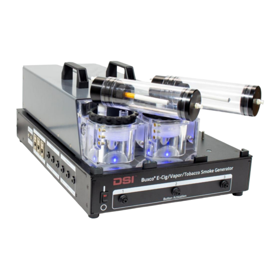
- Page 1 DSI Buxco® E-cigarette, Vapor, & Tobacco (EVT) Smoke Generator User Application Guide OVERVIEW This manual provides information on the setup and operation of the Buxco® E-cig Vape Tobacco (EVT) Smoke Generator. This document will provide an overview of the system components, proper assembly, and basic operation.
-
Page 2: Table Of Contents
Table of Contents TABLE OF CONTENTS Welcome ............................5 Scientific Background ........................6 Terminology ............................... 7 System Overview ..........................9 System Components..............................10 EVT Smoke Generator Controller ........................12 EVT Smoke Generator Station .......................... 15 QuickStart Guide - Example Experiment ..................20 Step 1 –... - Page 3 Start Puffing – Running an Experiment ......................67 Ending an Experiment and Saving Data ......................68 Information on Data Files ............................69 EVT Experiment Log.CSV ..........................69 Puff Log.CSV ..............................71 Signals.CSV ............................... 71 Setting up a 1 Generation E-Cig or Traditional Tobacco Cigarettes ........... 72 Fitting Options/Attachment Points .........................
- Page 4 Application Overview ............................104 Using the Buxco Inhalation Tower with the EVT Smoke Generator ........... 105 Application Overview ............................105 Setting Up the EVT Smoke Generator to the Inhalation Tower ................106 Lifespan, Maintenance, & Troubleshooting, Misc ..............107 Replacing and Cleaning the Bellows Assembly...................... 107 Cleaning the Bellows ............................
-
Page 5: Welcome
WELCOME Congratulations on joining the community of users worldwide who rely on DSI’s products to perform preclinical physiologic research. Thank you for your interest in DSI products. We are committed to providing you with quality products and services. This manual will help you get to know your E-Cig Vape Tobacco Smoke Generator (EVT). The structure of the manual was designed to guide you through setting up your DSI system. -
Page 6: Scientific Background
SCIENTIFIC BACKGROUND Research is being conducted to determine the risk of E-cigarettes and their potential relationship with chronic or acute lung disease. These studies are investigating if the use of e-cigarettes and vaping devices significantly increases the risk of developing lung diseases like asthma, bronchitis, emphysema, and chronic obstructive pulmonary disease (COPD). -
Page 7: Terminology
Figure 2 Labyrinth Seal Holder The EVT Smoke Generator is designed to generate aerosolized particulates from a cigarette, a 1st Generation E-Cig, a Pen, or a Mod device by creating “Standard Puffs”, following the standard puff profiles. TERMINOLOGY E-cigarettes, sometimes called E-cigs, vapes, or handheld electronic nicotine delivery systems (ENDS), are devices that create vapor by heating an element that atomizes a liquid solution. - Page 8 Figure 4 - 1st Generation E-cig 3. Pens – Advanced Personal Vaporizers (AVP). Larger than a cigarette, Pens often have a higher capacity battery, may contain a prefilled cartridge or refillable cartridge. These devices come with a manual switch for activating the vape solution. Figure 5 –...
-
Page 9: System Overview
SYSTEM OVERVIEW Data Sciences International has developed the Buxco® EVT Smoke Generator. The EVT Smoke Generator is designed to generate aerosolized particulates from a cigarette, 1st Generation E-Cig, Pen, or Mod devices. The EVT Smoke Generator is designed to meet both traditional cigarette and e-cig ISO standards for puff profiles, as well as provide the user the ability to customize puff parameters. -
Page 10: System Components
SYSTEM COMPONENTS This section will provide information on the components of the EVT Smoke Generator. Additional accessory items may be necessary depending on the type of device being sampled or study design. The following components can be part of an EVT Generator system. Some of these items are optional and are not necessary, depending on the exposure system configuration. - Page 11 Buxco EVT Station The EVT Station is a module that connects to the Controller and houses the hardware mechanisms necessary to create the “puff”. A high precision stepper motor generates a puff cycle. The motor controls the displacement of a piston-cylinder, which in turn produces pressure that actuates the bellows assembly.
- Page 12 In-Line Photometer Kit (optional) The Buxco In-Line Photometer can be used to measure the concentration levels of smoke or vape being delivered to an in-vitro or in-vivo exposure system. The In-Line Photometer measures aerosol concentration levels being delivered to the exposure system and provides that information to the Controller and reported out by the EVT software.
- Page 13 Figure 9 - EVT Smoke Generator Controller On/Off Switch It is used to turn the power to the EVT Controlled on and off. Button Activation Ports These three pneumatic ports are for use with optional Button-Activated Device Holder Kit(s). With the use of the kit(s), Pen and or Mod-type actuated devices can be triggered synchronously with puff generation (See EVT Button- Activation Kit under Auxiliary Attachments for more details).
- Page 14 Regulation Connectors The EVT Regulation Connectors are used in conjunction with the Pump Connectors to operate Supplemental Flow Unit(s). One I C, one Pump Connector, and one Regulation Connector is needed for each Supplemental Flow Unit. External Air Source The EVT Smoke Generator Controller requires an external air supply when used with the EVT Button-Activated Device Holder Kit.
- Page 15 EVT SMOKE GENERATOR STATION The EVT Smoke Station generates the desired puff profiles by pulling smoke/vapor into and out of the bellows assembly using a precision stepper motor. Each station contains a stepper motor, piston cylinder, and bellows assembly such that each station can function independently. Puffing with multiple stations can also be synchronized through the EVT Controller if desired, allowing the exhale ports to be combined.
-
Page 16: Evt Smoke Generator Controller
EVT Bellows Assembly Generating tobacco smoke or vape samples creates a harsh environment for sensitive electronic and mechanical components. Residue can cause early failure, particularly on moving parts and electronic components. The Buxco EVT Station is designed to capture and control tobacco and vape samples isolating the aerosol from the external environment and minimizing exposure to any sensitive EVT components. - Page 17 Figure 12 - Attaching the Station to the Controller Turn on the EVT Controller. Verify that power is being applied to the EVT Station by checking that the blue LED is illuminated, as shown by the picture in Figure 13. Note, LED may take a few seconds before lighting as the motor driver initiates, and the system verifies the station piston is at the “home”...
- Page 18 Also, make sure that the light in the station comes on when the Controller is powered up. If the light does not come on, press down on the back of the station to make sure it is fully seated into the Controller connector.
-
Page 19: Evt Smoke Generator Station
Figure 15 – ISO Standard Puffs for Tobacco and Vape The bellows, and the valves contained within the bellows lid, are the only moving parts exposed to the harsh environment of smoke or vape aerosol. The aerosol is contained within the bellows assembly, making them the only parts that require regular cleaning and or change out. -
Page 20: Quickstart Guide - Example Experiment
QUICKSTART GUIDE - EXAMPLE EXPERIMENT The following is an example of how the EVT Smoke Generator and the EVT Software would be used in an experiment. This example will walk you through each step needed to set up and run an experiment and show you how easy it is to begin using the EVT. -
Page 21: Step 2 - Connecting An Evt Station To The Controller
STEP 2 - CONNECTING AN EVT STATION TO THE CONTROLLER 1. Place the Controller on a flat, stable surface. 2. Lift the EVT Station by the handle and tilt the bellows side slightly downwards. 3. Insert the bellows side of the station into the alignment tabs located on the top right side of the Controller, as shown in the figure below. - Page 22 CAUTION: Before beginning any experiment, make sure to install/replace the Bellows Assembly only after the station has been powered up and in “home” position (LED light is on). Also make sure Bellows is in a compressed state and such that it is aligned with the bellows loading line.
-
Page 23: Step 3 - Performing A Leak Test
STEP 3 – PERFORMING A LEAK TEST The leak test assures that the system is sealed correctly. 1) Launch the EVT Software by double-clicking on the EVT Application Icon. 2) Click on Leak Test The Leak Test window will open. Instructions can be found on the top of the Leak Test screen. - Page 24 4) Click on the Test button. The Exhale leak test will begin. The pressure measurement should drop sharply negative, then decay for a time in a positive direction, and finally, stabilize to a flat line at negative pressure. After roughly 30 seconds, the Exhale Test Status should indicate that the test passed.
-
Page 25: Step 4 - Perform A Calibration And Puff Volume Measurement Test
STEP 4 – PERFORM A CALIBRATION AND PUFF VOLUME MEASUREMENT TEST The bellows assembly calibration is necessary to achieve accurate puff volumes. The calibration routine makes adjustments to the system to account for flow resistance and measured puff volume. Before beginning an experiment, it is recommended that you calibrate each station and capture a puff volume measurement. - Page 26 3) Connect the cable from the Mass Flow Meter to position “1” of the I C connections on the EVT Smoke Machine Controller. Make sure that the flow direction is aligned correctly with the direction indicated by the arrow on the top of the flow meter. Also, make note of the Slope and Offset values listed on the calibration label on the Mass Flow Meter.
- Page 27 5) Click on the “Puff Properties” button. 6) Select “First Generation E-Cig for the Cigarette Type, or Traditional Cigarette if using a Bell-shaped puff profile. 7) Make sure the “Standard Puff” checkbox is checked. 8) Click OK P a g e 014136-001 Rev 02 ©2021 Data Sciences International.
- Page 28 9) Click the “Calibrate” button. 10) The Calibration window will open. If this is the first time that you have calibrated using the Mass Flow Meter, a secondary window will open, allowing you to enter the Slope and Offset calibration values for a specific Mass Flow Meter. The Slope and Offset values are found on a label on the Mass Flow Meter.
-
Page 29: Performing A Calibration
First, the zero-flow baseline pressure is measured. This is quickly followed by puff cycles. During this time, the response time of the puff pressure is measured. This process is repeated five times, and the average response time is calculated. The status of the calibration process is indicated in the top left part of the window. - Page 30 12) When the calibration process is complete, the software will display “Measurement Complete” and the system will be ready to measure a puff volume. The Calibration window will indicate the current puff volume setting and the measured puff volume. The initial puff volume is 0.00 ml since we have not yet run the puff volume measurement process.
- Page 31 14) The EVT system will begin measuring a puff volume. First, it will measure the baseline flow. Then it will measure a puff volume. It will repeat this process three times. When completed, the configured volume and the measured volume will be displayed at the bottom of the window. 15) Once the calibration process is complete, click “Close.”...
- Page 32 The maximum allowable calibration error is ±4.0 ml around the expected volume. If the measured volume error is greater than 4.0 ml, the EVT software will indicate an error (see example error message below). If this occurs, repeat leak test to make sure you have a leak-tight system and check that your mass flow sensor is attached correctly as outlined in Step 4 –...
- Page 33 Launch the EVT Smoke Machine Software by double-clicking on the EVT Software Icon. The EVT Software Main Window should open. Make sure that the setting selections highlighted below are enabled (not grayed out), and the pressure graph is scrolling. P a g e 014136-001 Rev 02 ©2021 Data Sciences International.
- Page 34 5) Click on the “Measure Puff” button 6) This will open the Measure Puff window. The puff measurement window will indicate the current puff volume setting and the measured puff volume. The current measured puff volume is 0.00 ml since we have not yet run the puff volume measurement process.
- Page 35 9) The EVT system will begin measuring a Puff Volume. When completed, the configured volume and the measured volume will be displayed at the bottom of the window. 10) Once the Puff Measurement process is complete, click “Close.” P a g e 014136-001 Rev 02 ©2021 Data Sciences International.
-
Page 36: Measuring The Puff Volume
STEP 5 – CONFIGURE THE EXPERIMENT IN THE SOFTWARE CAUTION: Before beginning any experiment, make sure to install/replace the Bellows Assembly only after the station has been powered up and in “home” position (LED light is on). Also make sure Bellows is in a compressed state and such that it is aligned with the bellows loading line. -
Page 37: Step 6 - Pre-Experiment Puff Measurement
For this example, we will continue with the selected 1 Gen e-cig standard profile. Click the Start Puffing button. The Experiment Information window will open. If the Experiment Information window does not open, check to see if “Enable prompts for Experiment Information and Puff Measurement” was not enabled in the Program Settings window. - Page 38 Start the Puff Volume Measurement process by clicking the “Zero” button. The EVT system will quickly measure the flow offset. Once completed, click the “Measure” button. P a g e 014136-001 Rev 02 ©2021 Data Sciences International.
- Page 39 The EVT system will begin measuring a Puff Volume. When completed, the configured volume and the measured volume will be displayed at the bottom of the window. P a g e 014136-001 Rev 02 ©2021 Data Sciences International.
- Page 40 Once the Puff Measurement process is complete, click “Close.” STEP 7 - ATTACHING THE CIGRARETTE, E-CIG, MOD, OR PEN DEVICE & CHAMBERS Remove the Mass Flow Meter and attach the appropriate nicotine delivering device to the system, by referring to the following sections P a g e 014136-001 Rev 02...
- Page 41 • Setting up a 1 Generation E-Cig or Traditional Tobacco Cigarettes Setting Up a Mod or Pen Device P a g e 014136-001 Rev 02 ©2021 Data Sciences International.
- Page 42 • In-line Photometer Adapter • Adding the Supplemental Flow Unit to An EVT Smoke Machine Station Attach the appropriate chamber type to the system by referring to the sections: P a g e 014136-001 Rev 02 ©2021 Data Sciences International.
- Page 43 Using the Mass Dosing Chamber with the EVT Smoke Generator APPLICATION OVERVIEW The exposure of subjects with smoke or vape is conveniently done using DSI’s Mass Dosing system. Subjects are placed in a chamber and are exposed to smoke or vape for a desired time. The Mass Dosing system is particularly useful for exposures to tobacco.
-
Page 44: Step 7 - Attaching The Cigrarette, E-Cig, Mod, Or Pen Device & Chambers
Using the Buxco Inhalation Tower with the EVT Smoke Generator • Using the Mass Dosing Chamber with the EVT Smoke Generator P a g e 014136-001 Rev 02 ©2021 Data Sciences International. -
Page 45: Step 8 - Running The Experiment
STEP 8 - RUNNING THE EXPERIMENT When the device is attached and you are all ready to begin the experiment, click Start. Refer to Start Puffing – Running an Experiment for more information. The EVT Smoke Generator will begin puffing. The following sequence should occur 1) The status field in the main window will display “Initializing Puff”... - Page 46 5) Once the first puff is completed, the Status should display “Next puff in XX seconds” and start counting down. Note: For Tobacco Cigarettes, this time allows the user to discard exhausted cigarettes, and be ready to light the next one before the start of the next puff. 6) The next Puff will start, and the process will be repeated until the total number of puffs has been completed.
-
Page 47: Step 9 - Saving Puff Volume Data
STEP 9 - SAVING PUFF VOLUME DATA You can capture a post-experiment puff measurement and, at the same time, save information about the puff volume and concentration measurements in a comma-delimited file. The data file is stored at the location called out in the Experiment Information window. - Page 48 3) Click on the “Measure” button in the Post-Experiment Puff Measurement to capture a post-experiment Puff Volume measurement. Follow the same process as in Step 6 - Pre-Experiment Puff Measurement and connection of the mass flow meter in Performing a Calibration section (I C at the position 1, mass flow connected to Inhalation Port).
- Page 49 5) Click Save. This will save data for the experiment into a CSV file. This data file is stored at the location called out in the Experiment Information window. For more information on the format of the dataset, see Information on Data Files in section EVT Software User’s Manual in this manual.
-
Page 50: Evt Software User's Manual
EVT SOFTWARE USER’S MANUAL The EVT Software package, used in conjunction with the EVT Smoke Generator, will generate consistent aerosolized particles representative of what would be found in a “Standard Puff” from a tobacco cigarette, 1st Generation E-Cig, Pen, or Mod vape device. The EVT Software package allows the user to set the parameters of the sampling process, including the puff profile type, the puffing frequency, the inhalation and exhalation duration, the puff volume, and more. -
Page 51: Using Multiple Evt Controllers
Main Software Window Information Smoke Station Number and Serial This indicates the serial number of a Smoke Station and which slot it is Number attached to in the EVT controller Status The current status of the Station. This will indicate the following: •... - Page 52 P a g e 014136-001 Rev 02 ©2021 Data Sciences International.
-
Page 53: Evt Station Buttons
EVT STATION BUTTONS Station Buttons Start Puffing This feature Controls Puffing Actions. • Stop Puffing Start Puffing - Begins the experiment by starting the first puff Pause/Resume Puffing cycle. Puffing will continue until the total puff count is reached Save Puff Data or if Stop Puffing is selected. -
Page 54: Evt Station Graph
EVT STATION GRAPH This graph displays the pressure being measured by the EVT station in real-time. When puffing is occurring, the graph should show the pressure curve representing the puff. The X-axis and Y-axis of the pressure graph can be changed. - Page 55 E-cigarettes, and Tobacco Cigarettes. By selecting a Tobacco Cigarette, the bell-shaped puff profile is utilized. The e-cig trapezoid puff-profile is utilized for all other selections. To customize puff parameters, the user can un-check the “Standard Puff” box and set the Puff Volume, the Inhalation Duration (sec), the Exhalation Duration (sec), and the Puff Frequency in puffs per minute.
- Page 56 Puff Properties Dialog Window Cigarette Type This drop-down menu allows the user to select from four different types of cigarettes. This selection will set the puff attributes to the “Standard Puff” for that type of cigarette. Note: the “Standard Puff” checkbox needs to be checked to prepopulate and lock in standard puff values.
-
Page 57: Leak Test
Puff Properties Dialog Window Number of Bouts This is the number of bouts that will occur Puffs per Bout This is the number of puffs that are considered a bout. Interval Between Bouts (min) This is the time, in minute, from the start of a bout until the start of the subsequent bout. -
Page 58: Calibrate
Instructions Instructions on the steps for performing a leak test can be found on the top of the window Inhale Test Status This indicates the status and results of the Inhalation Leak Test. • Not tested – The test has not yet been started •... - Page 59 P a g e 014136-001 Rev 02 ©2021 Data Sciences International.
- Page 60 This will open the Calibration Window. Click on the “Calibrate” button. Calibration Status Provides information on the status of the calibration process • Top Left Measuring Pressure Zero Baseline • Starting Puff • Measuring Puff • Measurement ‘X’ of 5 complete, preparing for the next measurement Measured Time Constant Indication of the EVT Station’s response time during the rising edge of...
- Page 61 Puff Measurement Instructions Instructions on how to perform a calibration are shown on the top of Top Left the Calibration Window Puff Measurement Status Provides information on the status of the Puff Measurement process • When clicking the “Zero” button Measuring Flow Offset •...
-
Page 62: Measure Puff
MEASURE PUFF The Measure Puff button is used to measure and record the l puff volume as measured using the EVT Puff Volume Measurement Kit. To access the Measure Puff window, click Measure Puff on the Main Window. This will open the Measure Puff window. P a g e 014136-001 Rev 02 ©2021 Data Sciences International. -
Page 63: Program Settings
Instructions Instructions on how to set up the hardware to measure the puff volume using the mass flow sensor. Zero When selected, this measures the value of the Mass Flow Meter with no airflow. It is used to capture any offset inherent in the Mass Flow Unit. Measure When activated, this starts the puff measurement process Configured Puff Volume... -
Page 64: Hardware Menu
Program Settings Windows Prompts • When the experiment is started, the Experiment Information window will open. Information can be added or modified before starting the experiment. • At the end of the experiment, the Experiment Information window will open, allowing the user to make changes to experiment information and to save the puff pressure measurements to an excel file. - Page 65 Hardware Menu Drop Down Start All This allows the user to start the puffing synchronously across all attached stations on the EVT Smoke Generator. Smoke Station Info… Clicking on the “Smoke Station Info…” button opens the Smoke Station Information window. Lifetime Puffs: Each station has a warranty lifespan of 100,000 puffs.
- Page 66 Hardware Menu Drop Down Supplemental Flow Units… Up to 3 supplemental flow uses can be attached to the system. In this dialog box, the user can set the flow units for each supplemental unit. Once the user enters a value greater than 0 and clicks OK the supplemental flow unit(s) will turn on.
-
Page 67: Experiment Information
EXPERIMENT INFORMATION Enabling the Experiment Information and Puff Measurements option allows the user to name the experiment and provide a description of the experiment. It also allows the user to set criteria for automatically stopping puff cycles. By default, the system will stop when the specified number of puffs has been completed. When the system is operated with an In-Line Photometer Kit, there are additional options to automatically stop based upon concentration or Total Exposed Material. - Page 68 EXPERIMENT WINDOW DIALOG At the beginning and end of the experiment, the Experiment Information Window will open. Experiment Name This is the name of the file that is used to store the results of the experiment. The format of the data file is EXPERIMENT 1.csv. Note: If the same experiment name is used more than once, each subsequent data set saved will be appended to the end of the previous experiment file.
- Page 69 CRITERIA TO AUTOMATICALLY STOP PUFFING There are times when you may want to stop an experiment before it has completed the total number of puffs. For example, if the device, E-Cig Pen or Mod, runs out of fluid, you may want to stop puffing. The EVT Smoke Machine Controller can monitor the particle concentration levels using the EVT In-Line Photometer Adapter (Optional).
- Page 70 Experiment Information Dialog Window Stop automatically when Total When selected, the EVT Controller will stop puffing when the total Exposed Material is X mg. amount of exposed material reached the set level, prior to reaching the maximum number of puffs. The total amount of exposed material is measured in mg.
-
Page 71: Saving And Loading Profiles & Calibrations
SAVING AND LOADING PROFILES & CALIBRATIONS The EVT Software allows you to save Experiment Profile Information. By saving the Experiment Profile, it can be loaded later to reproduce the experiment. Experiment information is saved to an XML file. The XML file contains information such as Photometer and Supplemental Flow settings, puff properties settings, graph scaling, the location where results are stored, as well as an indicator if the Experiment Information option was selected. - Page 72 Experiment Window Dialog for more information on the fields in this dialog. If a supplemental flow unit is associated with the station, the station information will include the the real-time value of the supplemental flow along with the ending criteria specified in the “Criteria to Automatically Stop Puffing” as shown in the screenshot below.
-
Page 73: Ending An Experiment And Saving Data
ENDING AN EXPERIMENT AND SAVING DATA When an experiment is completed, the Experiment Information Window will open. The user is allowed to enter or modify the Experiment Description, capture a Post-Experiment Puff Volume Measurement, and save the Experiment Data. Figure 18 – Ending an Experiment within the Experiment Information Dialog INFORMATION ON DATA FILES The EVT Software saves data from the experiment into CSV files. - Page 74 Column Name Format Definition Note: If the experiment name is not changed, and an additional experiment is run, the data will be appended to the experimental data set. Experiment Text User Input This is a description of the experiment entered by the user in Example: Description the Experiment Information Window.
-
Page 75: Puff Log.csv
Column Name Format Definition MOD Vaporizer Time Constant 1 Number This is the rising edge time constant determined during the Reported in Seconds calibration process. It is measured each time a calibration is Examples: performed. The values are reported in seconds. Calibration 0.00025 will fail if the value exceeds 0.001 seconds. -
Page 76: Setting Up A 1 St Generation E-Cig Or Traditional Tobacco Cigarettes
SETTING UP A 1 GENERATION E-CIG OR TRADITIONAL TOBACCO CIGARETTES The EVT Smoke Generator Controller can be used to collect aerosolized samples from 1 Generation Cigarettes (E- Cigs) and traditional tobacco cigarettes. This is done by drawing air through the E-Cig or cigarette into the Inhale Port of the bellows assembly like the way Mod or Pens are sampled. - Page 77 when using the labyrinth seal assembly with e-cigs to allow additional insertion length and support for the e-cig. Figure 19 – Labyrinth Assembly 2) The 1st Generation E-Cig can alternatively be held in place using the elbow connector (014008-001) and a short piece of tubing.
-
Page 78: Lighting
LIGHTING Traditional Tobacco Cigarettes must be lit at the beginning of the experiment, and after each cigarette is exhausted and needs to be replaced with a new cigarette. This must be done at the beginning of a puff, so the action of drawing air into the cigarette will help light the tobacco. -
Page 79: Puff Settings - Traditional Cigarettes
Figure 21 More information on how to set the Puff Properties can be found in the Puff Properties section in the EVT Software User’s Manual part of this manual. PUFF SETTINGS – TRADITIONAL CIGARETTES The EVT software, used in conjunction with the EVT Controller, can sample a traditional tobacco cigarette by drawing air through the test cigarette while it is lit. - Page 80 The EVT Software can be used to adjust the “puff” attributes by allowing the user to set the parameters of the puff. A preset standard “Puff” for traditional tobacco cigarettes based on ISO standards can be selected, or the puff attributes can be customized to a variety of requirements. For traditional tobacco cigarettes, ISO 3308:2012 calls for a puff volume of 35ml with an inhalation duration of 2 seconds and a puff frequency of 1 puff per minute.
-
Page 81: Sidestream Smoke Capture
More information on how to set the Puff Properties can be found in the Puff Properties section in the EVT Software User’s Manual part of this manual. SIDESTREAM SMOKE CAPTURE The Labyrinth Assembly also has a feature that can be used to capture sidestream smoke from the cigarette. It utilizes a containment cover that is attached to the assembly, which will prevent the smoke from escaping from the system. - Page 82 • (1) Labyrinth Assembly • (2) Labyrinth Assembly Cover • (3) Labyrinth Assembly End Cap • (4) Intake Port Connector • (5) Exhaust Port Connector To use the sidestream smoke feature 1) Make sure that the exhaust tube is connected to the exhaust connector (5), and a vacuum is applied. 2) Make sure the Intake Port connector (4) is left open.
-
Page 83: Setting Up A Mod Or Pen Device
SETTING UP A MOD OR PEN DEVICE The EVT Generator can be used to collect aerosolized samples from devices such as Mods or Pens that are activated with button ignition. The EVT Controller, in conjunction with the Buxco EVT Button-Activated Device Holder Kit, can activate the Mod or Pen Device by pushing the ignition button during the “puff”... - Page 84 Directions for installing a Mod or Pen device on to the EVT Button-Activated Device Holder Kit. 1) Attach the C-Clamp (B) to the Tilt Platform (A) Place the C-Clamp to on top of the Tilt Platform and secure it by tightening the attachment screw located below the top of the platform.
-
Page 85: Attaching Flow Path Tubing For The Inhalation Port
3) Place the Mod (E) or the Pen (F) on to the Cradle and clamp it into place with the clamp screw by rotating it counterclockwise until snug. Figure 27 ATTACHING FLOW PATH TUBING FOR THE INHALATION PORT DSI provides a Barbed Drip Tip Adaptor, which is used to connect the Mod Tank. This Drip Tip Adaptor is then connected with a high-temperature silicone tubing to an elbow connector attached to the Inhale Port of the EVT bellows assembly. -
Page 86: Angle/Height Adjustment
Figure 28 - Mod and Pen Connections ANGLE/HEIGHT ADJUSTMENT The Mod or Pen is held in place by the EVT Button Activated Device Holder Kit. The Holder Kit can be raised and lowered as well as tilted backward to hold the Mod or Pen in place properly. The height of the Mod or Pen should be set, so the device is slightly lower than the connection to the Inhale Port on the bellows assembly. -
Page 87: Evt Button-Activated Device Holder Kit
The Mod should also be tilted backward so the fluid in the Mod tank stays in the tank and will not flow into the barbed drip tip adapter connected to the front of the Mod. It is suggested that the Mod or Pen Device should be tilted backward at roughly a 30°... -
Page 88: Setting The Air Pressure For The Evt Button Activation Device Holder Kit
Button activation is done using a small cylinder located on the tilt platform. This cylinder is activated by air from the EVT Smoke Machine Controller. The cylinder is driven by an external regulated air source attached to the Controller’s Air Source Connector. SETTING THE AIR PRESSURE FOR THE EVT BUTTON ACTIVATION DEVICE HOLDER KIT The amount of pressure needed to trigger the ignition button on electronic nicotine delivery devices can vary from device-to-device. -
Page 89: Puff Settings
PUFF SETTINGS The EVT software, used in conjunction with the EVT Controller, can sample the Mod device by drawing air through the Mod while the EVT Holder Kit activates the ignition button. The sample of vape is acquired by pulling air through the Mod in what is called a “puff.”... - Page 90 Figure 31 - The flow profile is characterized by a trapezoidal shape for the MOD vaporizer and the Mid-Size “Pen” E-Cig More information on setting Puff Properties can be found in the Puff Properties sections of this manual. P a g e 014136-001 Rev 02 ©2021 Data Sciences International.
-
Page 91: Evt Smoke Machine Kits
EVT SMOKE MACHINE KITS: EVT PUFF VOLUME MEASUREMENT KIT (MASS FLOW SENSOR) The EVT Puff Volume Measurement Kit is used to calibrate or validate the puff volume generated by the EVT Station. The puff volume is measured as a part of the calibration process, where it is used to adjust the station piston displacement to achieve the target volume. -
Page 92: In-Line Photometer Adapter
IN-LINE PHOTOMETER ADAPTER Real-time smoke or vape concentration levels can be measured using the EVT In-line Photometer Adapter. The photometer probe can be located on the “Exhalation” line from the EVT Station, as shown in Figure 33 - EVT with Photometer Kit, and or post-dilution and or mixing with the use of the Buxco Supplemental Flow Unit(s) or EVT Reservoir Kit mixing vessel. -
Page 93: Physical Setup (Port)
PHYSICAL SETUP (PORT) The following section outlines the physical connections to attach the photometer to a Buxco In-Line Photometer Adapter for measuring smoke/vape concentration levels from the EVT Generator. Figure 34 - Photometer Kit To attach the photometer to the EVT Generator: 1. - Page 94 From Supplemental Flow Unit (Optional) 3/8” fitting 5/16” fitting Figure 36 – Photometer Tubing Connection 5. Attach the power cable from the power input port on the bottom of the Casella digital handheld component to a wall outlet. 6. Attach the photometer cable from the 2.5mm output port on the bottom of the Casella digital handheld component to the jack on the EVT Generator labeled Photometer Inputs.
-
Page 95: Casella Handheld Monitor Setup
CASELLA HANDHELD MONITOR SETUP The Casella Monitor needs to be set up to scale the output voltage for a fixed specified concentration range. The EVT software is required to be configured to match this setting, which is covered in the next section. To set up the handheld monitor: 1. -
Page 96: Photometer Calibration
When launching the EVT Software, select Photometer from the Hardware menu. The Photometer Setup window will appear and allow users to adjust the software to match the photometer settings. Use the drop-down menu to select the same sensitivity setting for both Photometer jacks (Port and Inflow) set in the Casella Handheld Monitor. PHOTOMETER CALIBRATION The Casella CEL-712 Photometer is a sensitive measuring instrument. - Page 97 5. Squeeze and release the purge bellows 5 or 6 times over a 10 second period to inject clean air into the chamber and removes possible contamination of particulates that might have settled on the optical components inside the probe. 6.
- Page 98 SETTING THE SPAN The Microdust Pro is supplied with an optical ‘Calibration Insert,’ which is used to establish a known instrument sensitivity or ‘Span.’ When inserted into the probe, the Calibration Insert creates a stable and fixed scattered effect and signal level. CAUTION.
-
Page 99: Connecting The Evt In-Line Photometer Kit
4. Press the Yes soft key to start the calibration. An automatic delay occurs after pressing the Yes soft key to allows the reading to stabilize. A progress bar is displayed during the calibration. 5. After successful calibration, the display should show a reading within ± two digits of the value shown on the Calibration Insert. - Page 100 Figure 38 - Photometer Kit with Supplemental Flow Unit is a configuration that allows the EVT system to vary the flow rate of the supplemental flow and, in turn, the aerosol concentration levels. Figure 38 - Photometer Kit with Supplemental Flow Unit As shown in Figure 39 - Photometer Kit with Supplemental Flow Unit and 3 Stations, for the maximum particle concentration levels, the output of up to three EVT Smoke Stations can be connected through a manifold.
-
Page 101: Gravimetric Calibration
Figure 39 - Photometer Kit with Supplemental Flow Unit and 3 Stations GRAVIMETRIC CALIBRATION Items Required: • EVT Generator • EVT Station • Casella CEL-712 Photometer • Inline Photometer Kit • Supplemental Flow Unit • Test article (E-cig, Mod, etc.) •... - Page 102 reveal the mass of aerosol accumulated in the filter. A second measure of mass is calculated from photometer readings, using the photometer’s recorded average concentration multiplied by volumetric flow and test duration. The gravimetric calibration factor is simply the ratio between the measured mass accumulated in the filter, and the mass registered by the photometer.
- Page 103 Figure 40 - Photometer Kit with Supplemental Flow Unit and 3 Stations for Gravimetric Calibration to Pull Aerosol Test Setup Instructions: 1. Set up the photometer: Make sure that “Factor” is set to 1. The photometer does not need to be attached to the EVT station b.
- Page 104 3. Route tubing from exhale ports to the inline photometer adapter, making sure there is an inlet open to ambient air between the station and the photometer (for dilution.) 4. Attach the 22 nm filter to the bottom of the Inline photometer via tubing. 5.
-
Page 105: Supplemental Flow Unit - Setting Flow
SUPPLEMENTAL FLOW UNIT – SETTING FLOW The Supplemental Flow Unit is used to provide additional, regulated flow into the system. It contains a mass flow sensor, a pump, and a variable valve used to regulate flow to the user-defined target flow settings specified within the EVT software. -
Page 106: Adding The Supplemental Flow Unit To An Evt Smoke Machine Station
ADDING THE SUPPLEMENTAL FLOW UNIT TO AN EVT SMOKE MACHINE STATION To add the supplemental Flow Unit to an EVT Smoke Station, connect the Supplemental Flow Unit to one side of a “T” connector (supplied in the Supplemental Flow Unit Kit). Connect the other side of the “T” connector to the exhale port of the Smoke Machine Station. - Page 107 Figure 43 - Electrical Connections for the Supplemental Flow Unit EVT INLINE SMOKE RESERVOIR KIT The reservoir Kit is an optional accessory that can be used to either aid in supplemental flow mix and or combine several EVT Stations exhaust flows for increased particle concentration levels. Up to four devices can be connected to the reservoir, including EVT Stations, Multiple EVT Stations, and Supplemental Flow Units.
-
Page 108: Using The Mass Dosing Chamber With The Evt Smoke Generator
USING THE MASS DOSING CHAMBER WITH THE EVT SMOKE GENERATOR APPLICATION OVERVIEW The exposure of subjects with smoke or vape is conveniently done using DSI’s Mass Dosing system. Subjects are placed in a chamber and are exposed to smoke or vape for a desired time. The Mass Dosing system is particularly useful for exposures to tobacco. -
Page 109: Using The Buxco Inhalation Tower With The Evt Smoke Generator
USING THE BUXCO INHALATION TOWER WITH THE EVT SMOKE GENERATOR APPLICATION OVERVIEW Since the pulmonary system is considered a vital organ, it is essential to have instruments allowing researchers to study the effects of environmental toxins and chemical entities when inhalation is the primary route of exposure. Inhalation research often presents the challenge of greater variability in toxin delivery as compared to other administration methods such as intravenous injection or an oral dose. -
Page 110: Setting Up The Evt Smoke Generator To The Inhalation Tower
of the tower. The unit regulates the pressure in the outer column to achieve a target pressure, which is either slightly above or below zero, as selected by the user. This pressure is monitored in real-time, providing instant feedback and uses rapid response valves to allow the excess pressure to vent as needed For more information on the configuration and use of the Buxco Inhalation Tower, please reference the Buxco Inhalation Tower Application Guide. -
Page 111: Lifespan, Maintenance, & Troubleshooting, Misc
Figure 46, Electrical Connections Supplemental Flow Unit and In-Line Photometer Kit LIFESPAN, MAINTENANCE, & TROUBLESHOOTING, MISC REPLACING AND CLEANING THE BELLO WS ASSEMBLY The bellows assembly, which contains the bellows and the bellows lid with inhale and exhale check valves, are exposed to contaminants from the tobacco smoke and vape. -
Page 112: Performing An Internal Leak Test
e) With the bellows in a fully compressed state, insert a new bellows assembly into the Bellows Chamber. When installed into the bellows chamber, the bottom of the bellows must line up within the Bellows Alignment Marks on the bellows chamber. This is considered the home position for the bellows. g) Place the Bellows Ring (1) on top of the bellows assembly and screw the assembly together by rotating the ring clockwise until hand tightened. - Page 113 2) Click on Leak Test The Leak Test window will open. Instructions can be found on the top of the Leak Test screen. The status of the leak test can also be seen at the top of the screen. 3) Start by inserting a leak test plug into the Inhale port of the bellows cap (leak test plugs are provided in the station Accessory kit).
- Page 114 4) Click on the Test button. The “Exhale” leak test will begin. The pressure measurement should drop sharply negative, then decay for a time in a positive direction. Then the pressure should stabilize to a flat line at a negative level. After roughly 30 seconds, the Exhale Test Status should indicate that the test passed.
-
Page 115: Performing A Calibration
If the leak test fails, try the following: 1) Most likely, the issue would be a seal between the bellows and the chamber. Apply a light coat of grease to the bottom of the bellows assembly, reinsert into the bellows chamber, and try the leak test again. 2) Look for small cracks in the Bellows Lid. - Page 116 Launch the EVT Smoke Machine Software by double-clicking on the EVT Software Icon. The EVT Software Main Window should open. Make sure that the setting selections highlighted below are enabled (not grayed out), and the Pressure graph is scrolling. P a g e 014136-001 Rev 02 ©2021 Data Sciences International.
- Page 117 5) Click on the “Puff Properties” button. 6) Select “First Generation E-Cig for the Cigarette Type, or Traditional Cigarette if using a Bell-shaped puff profile. 7) Make sure the “Standard Puff” checkbox is checked. 8) Click OK P a g e 014136-001 Rev 02 ©2021 Data Sciences International.
- Page 118 9) Click the “Calibrate” button. 10) The Calibration Window will open. If this is the first time that you have calibrated using a particular Mass Flow Meter, a secondary window will open, allowing you to enter the Slope and Offset calibration values for the Mass Flow Meter. The Slope and Offset values are found on a label on the Mass Flow Meter.
- Page 119 First, the zero-flow baseline pressure is measured. This is quickly followed by a puff cycle. During this time, the response time of the puff pressure is measured. This process is repeated five times, and the average response time is calculated. The status of the calibration process is indicated in the top left part of the window.
- Page 120 12) When the calibration process is complete, the software will display “Measurement Complete” and the system will be ready to measure a puff volume. The Calibration window will indicate the current puff volume setting and the measured puff volume. The initial puff volume is 0.00 ml since we have not yet run the puff volume measurement process.
- Page 121 14) The EVT system will begin measuring a puff volume. First, it will measure the baseline flow. Then it will measure a puff volume. It will repeat this process three times. When completed, the configured volume and the measured volume will be displayed at the bottom of the window. 15) Once the calibration process is complete, click “Close.”...
-
Page 122: Custom Cradle - Customer Access To Basic Cradle Geometry (Step File)
The maximum allowable calibration error is ±4.0 ml around the expected volume. If the measured volume is greater than 4.0 ml, the EVT software will indicate an error. If this occurs, repeat leak test to make sure you have a leak-tight system and check that your mass flow sensor is attached correctly. CUSTOM CRADLE –... -
Page 123: Kits, Contents & Uses
KITS, CONTENTS & USES REPLACEMENT EVT BELLOWS ASSEMBLIES The Bellows Assemblies are a consumable part that will need to be cleaned or replaced frequently. How often the bellows and valves will need to be cleaned or replaced varies depending on the amount of exposure to contaminants over time. -
Page 124: Evt Smoke Machine Controller Accessory Kit - Parts List
EVT SMOKE MACHINE CONTROLLER ACCESSORY KIT – PARTS LIST The following outlines the components available in the EVT Smoke Machine Controller Accessory Kit. Replacement Kit Part Number: 601-2261-001 Find Number Description Quantity DSI Part Number FIT, PC, ¼” – 5/16” ACETAL 008750-001 TUBE, CLEAR, POLYUR, 3/16”x5/16”... -
Page 125: Evt Smoke Station Accessory Kit - Parts List
EVT SMOKE STATION ACCESSORY KIT – PARTS LIST The following outlines the components available in the EVT Smoke Station Accuracy Kit. Replacement Kit Part Number: 601-2262-001 Find Number Description Quantity DSI Part Number TUBING REDUCER 1/4" TO 3/8" 006169-003 FIT, LUER, MALE, PLUG, WHITE 008667-001 FIT,LUER,FEMALE,1/4-28,WHT,NYL 008689-001... -
Page 126: Evt Cigarette Holder And Containment Tube - Parts List
EVT CIGARETTE HOLDER AND CONTAINMENT TUBE – PARTS LIST The following outlines the components that are available in the EVT Cigarette Holder and Containment Tube kit. Replacement Kit Part Number: 601-2064-001 Find Number Description Quantity DSI Part Number ADAPTER, LABYRINTH SEAL, EVG 013901-001 CAP, LABYRINTH SEAL, EVG 013902-001... -
Page 127: Evt Button-Activation Device Holder Kit - Parts List
EVT BUTTON-ACTIVATION DEVICE HOLDER KIT – PARTS LIST The following outlines the components available in the EVT Button-Act Device Holder Kit. Replacement Kit Part Number: 601-2070-001 Find Number Description Quantity DSI Part Number CLAMP ECIG BUTTON ACTIVATOR 014066-001 CAMERA MOUNT, TILT ACCESS 014047-001 FLANGE BIMBA CYL ACTIVATOR 014067-001... -
Page 128: Evt Puff Volume Measurement Kit - Parts List
EVT PUFF VOLUME MEASUREMENT KIT – PARTS LIST The following outlines the components available in the EVT Puff Volume Measurement Kit. Replacement Kit Part Number: 601-2065-001 Find Number Description Quantity DSI Part Number CLAMP ECIG BUTTON ACTIVATOR 014066-001 CAMERA MOUNT, TILT ACCESS 014047-001 FLANGE BIMBA CYL ACTIVATOR 014067-001... -
Page 129: Evt In-Line Smoke Reservoir - Parts List
EVT IN-LINE SMOKE RESERVOIR – PARTS LIST The following outlines the components available in the EVT In-Line Smoke Reservoir kit. Replacement Kit Part Number: 601-2066-001 Find Number Description Quantity DSI Part Number LID, AREOSOL CONCENTRATION BAL 104077-001 FIT, PC, 1/4NPT-3/8”, NICKEL 007873-001 GASKET, SILICONE, WIDE MOUTH 014079-001... -
Page 130: In-Line Photometer Kit - Parts List
IN-LINE PHOTOMETER KIT – PARTS LIST The following outlines the components available in the In-Line Photometer kit. Replacement Kit Part Number: 601-3192-001 Find Number Description Quantity DSI Part Number ADAPTER, CENTER, IN-LINE PHOTO 012157-001 ADAPTER, TOP, IN-LINE PHOTOMTR 012166-001 O-RING, #118, BUNA-N 009443-001 CAP SCREW, 6/32 X 1/2"... -
Page 131: Specifications
SPECIFICATIONS SPECIFICATION Station Longevity: 100,000 cycles min Station Connect/Disconnect 1,000 min Bellows Longevity 10,000 puffs, min E-Cig Standard Puff, as per ISO 20768 Puff Volume: 55ml ± 0.6ml as calibrated and measured with provided 1kPa flow restrictor, or ±3.7 ml with pressure drop from 0 to 3kPa* b. -
Page 132: Dimensions
DIMENSIONS WEIGHT EVT Smoke Machine Controller – 11.5 lbs. ECT Smoke Machine Station – 9.0 lbs. OPERATING ENVIRONMENTAL CONDITIONS • Indoor use • Altitude up to 2000 m; • Ambient temperature 4°C to 40°C • 4°C to 40°C; 10% - 80% Rh, Non-condensing •... - Page 133 Only use a detachable power cord (AC/DC adapter) that allows for protective earthing and is a minimum of 18 AWG. This cord will need to have appropriate agency approvals, such as UL, CSA. P a g e 014136-001 Rev 02 ©2021 Data Sciences International.
-
Page 134: Technical Support
TECHNICAL SUPPORT DSI™ is available to help you with your questions and concerns. Should you hit a roadblock or need some additional training, please feel free to contact us. We are happy to help! DSI TECHNICAL SUPPORT —NORTH AMERICA Email: Support@datasci.com DSI TECHNICAL SUPPORT —EUROPE Email:...
Need help?
Do you have a question about the DSI Buxco E-cigarette, Vapor, & Tobacco (EVT) Smoke Generator and is the answer not in the manual?
Questions and answers