
Related Manuals for Nice Pro-FDG


Summary of Contents for Nice Pro-FDG
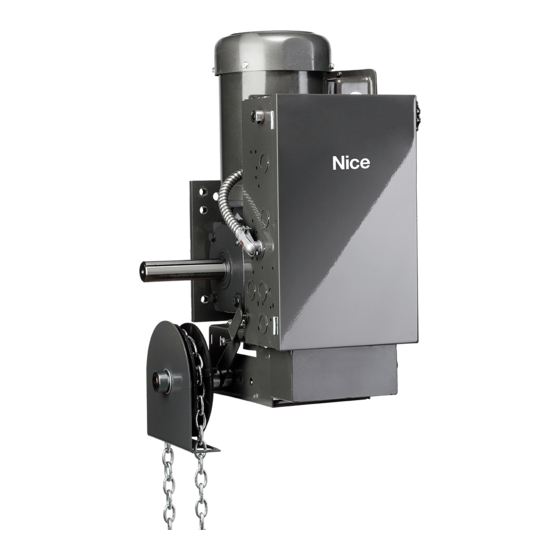
- Page 1 Pro-FDG Automation for high performance industrial doors Instructions and Warnings for Installation and Use...
-
Page 2: Table Of Contents
Floor Level Disconnect Pro-FDG Assembly . . . . . . . . . . . . . . . . . . -
Page 3: Warranty
Warranty Nice North America warrants that materials and workmanship are free from defects for a period of four (4) years. The start of the warranty will be determined by the date of invoice. Materials returned to Nice deemed defective after examination will be returned at the option of Nice with repaired, new, or re-manufactured parts. -
Page 4: Electrical Connections
EACH INDIVIDUAL COMMERCIAL DOOR OPERATOR MUST HAVE IT’S OWN DEDICATED POWER SUPPLY • NICE HIGHLY RECOMMENDS THAT EACH INDIVIDUAL COMMERCIAL DOOR OPERATOR HAVE AN EXTERNAL CIRCUIT BREAKER OR FUSED DISCONNECT WARNING COMPARE AVAILABLE POWER SUPPLY VOLTAGE TO OPERATOR NAMEPLATE PRIOR TO ELECTRICAL CONNECTION . -
Page 6: Header Assembly Installation
Header Assembly Installation Dimensions in Parenthesis are in millimeters (left hand door shown) HEADER ASSEMBLY LOCK WASHER BOLT CURTAIN TO THE BACK OF THE DRIVE BARREL THE ENDPLATES HAVE THREADED HOLES TO INSTALL THE HEADER MOUNTING BOLTS CURTAIN TO THE FRONT OF THE IDLER BARREL LINTEL... -
Page 7: Install Operator
Install Operator Dimensions in Parenthesis are in millimeters (left hand door shown) OPERATOR MOUNTING PLATE DRIVE SYSTEM DOOR SPROCKET OPERATOR BOLT FLAT WASHERS LOCK WASHERS LOCK WASHER FLAT WASHER BOLT (i) POSITION AND BOLT THE OPERATOR TO THE MOUNTING PLATE ON THE LOWER SLOT/HOLE SET CLOSEST TO THE ENDPLATE. -
Page 8: Install Qd Sprockets
Install QD Sprockets Dimensions in Parenthesis are in millimeters (left hand door shown) DRIVE SPROCKET KEYSTOCK DOOR DRIVE SPROCKET C/W QD BUSHING AND HARDWARE USE THREADED HOLES IN SPROCKET “QD” BUSHING BOLT TORQUE SPECIFICATION “QD” BUSHING SIZE BOLT TORQUE USE THROUGH HOLES IN BUSHING 108 IN . -
Page 9: Floor Level Disconnect Pro-Fdg Assembly
Floor Level Disconnect Pro-FDG Assembly... -
Page 10: Moving Door Warning Placard
Moving Door Warning Placard Install Moving Door Warning Placard in the conspicuous place near Open/Close/Stop station as indicated. -
Page 11: Operator Maintenance
Operator Maintenance WARNING TO REDUCE THE RISK OF INJURY OR DEATH: DO NOT ATTEMPT TO SERVICE THE OPERATOR UNLESS POWER SUPPLY HAS BEEN DISCONNECTED . • Inspect manual function of the door every 3-months. Make sure that door runs smoothly. If door does not manually open or close freely, have a qualified service person make repairs. -
Page 12: Inspection/Maintenance For Dr. 71-Dr.225 Brakemotors
Inspection/Maintenance for Dr. 71-DR.225 Brakemotors Basic Structure Motor w/brake endshield Stud [95] Sealing ring [22) Hex head screw [57] Conical coil spring [550] Pre-assembled brake [32) Circlip [58) Setting nut [900) Screw [35] Fan guard [59) Parallel pin [901) Sealing [36] [62] Circlip... -
Page 13: Inspection Steps
Inspection/Maintenance for Dr. 71-DR.225 Brakemotors Inspection Steps WARNING: Risk of crushing if the drive starts up unintentionally. Severe or fatal injuries. • Isolate the motor, brake, and forced cooling fan, if installed, from the power supply before starting work, safeguarding them against unintentional re-start. -
Page 14: Be05-Be2 Brakes (Dr.71-Dr.80) - Basic Structure
Inspection/Maintenance for Dr. 71-DR.225 Brakemotors BE05-BE2 brakes (DR.71-DR.80) - Basic Structure [42] Brake bearing end shield [61] Hex nut [49) Pressure plate [49] Pressure plate [65] Pressure ring [68] Brake disk [50] Brake spring (normal) [66] Rubber sealing collar [73] Terminal disk [54] Magnet, complete... -
Page 15: Setting The Working Air Gap Of Be05-Be32 Brakes
Inspection/Maintenance for Dr. 71-DR.225 Brakemotors Setting the working air gap of BE05-BE32 brakes WARNING: Risk of crushing if the drive starts up unintentionally. Severe or fatal injuries. • Isolate the motor, brake, and forced cooling fan, if installed, from the power supply before starting work, safeguarding them against unintentional re-start. - Page 16 Inspection/Maintenance for Dr. 71-DR.225 Brakemotors 6. BE05-BE20: Tighten the hex nuts [61] until the working air gap is set correctly, see chapter "Technical Data" (page 125) BE30-BE32: Tighten the hex nuts [61] until the working air gap is 25 mm. 7.
-
Page 17: Replacing The Brake Disk Of Be05-Be32 Brakes
Inspection/Maintenance for Dr. 71-DR.225 Brakemotors Replacing the brake disk of BE05-BE32 brakes In addition to the brake elements listed in column "BE brake", see chapter "Inspection and maintenance intervals" (page 76), check the hex nut nuts [61] for wear when you replace the brake disk. You must always replace the hex nuts [61] when you replace the brake disk. - Page 18 Inspection/Maintenance for Dr. 71-DR.225 Brakemotors 9. With manual brake release: Use setting nuts to set the floating clearance "s" between the conical coil springs {pressed flat) and the setting nuts {see following figure). This floating clearance "s" is necessary so that the pressure plate can move up as the brake lining wears. Otherwise, reliable braking is not guaranteed.
-
Page 19: Changing The Braking Torque Of Be05-Be32 Brakes
Inspection/Maintenance for Dr. 71-DR.225 Brakemotors Changing the braking torque of BE05-BE32 brakes The braking torque can be altered in stages. • by changing the type and number of brake springs • by changing the complete magnet (only possible for BE05 and BE1) •... -
Page 20: Changing The Magnet Of Be05-Be32 Brakes
Inspection/Maintenance for Dr. 71-DR.225 Brakemotors Changing the magnet of BE05-BE32 brakes WARNING: Risk of crushing if the drive starts up unintentionally. Severe or fatal injuries. • Isolate the motor, brake, and forced cooling fan, if installed, from the power supply before starting work, safeguarding them against unintentional re-start. -
Page 21: Replacing The Brake Of Dr.90-Dr.225
Inspection/Maintenance for Dr. 71-DR.225 Brakemotors Replacing the brake of DR.90-DR.225 WARNING: Risk of crushing if the drive starts up unintentionally. Severe or fatal injuries. • Isolate the motor, brake, and forced cooling fan, if installed, from the power supply before starting work, safeguarding them against unintentional re-start. -
Page 22: Notes
Notes... - Page 23 Notes...
- Page 24 Nice North America 877-888-1116 c/o Customer Service 5919 Sea Otter Place, Suite 100 Technical Support Hours: Carlsbad, CA 92010 M – F, 8:00 a .m . – 6:00 p .m . ET Niceforyou.com ©2024 Nice North America LLC. All rights reserved. Rev-A...
Need help?
Do you have a question about the Pro-FDG and is the answer not in the manual?
Questions and answers