
Related Manuals for Nice DC Blue Absolute


Summary of Contents for Nice DC Blue Absolute
- Page 1 DCBABS2024_HW07_00_FW01_00_INSTALLER (02372-100) Installer Instructions Domestic Roll-Up Door Operator www.niceforyou.com/za...
-
Page 2: Warranty
Introduction. Page 3 Be Safe! Instructions, warnings and obligations. Page 4 Technical specifications. Page 5 Component identification and descriptions. Hardware installation - Mechanical. Page 6 Fitting the motorhead, weight bar and control box. Hardware installation - Electrical. Page 11 Control card wiring and layout. Control card programming and setup. -
Page 3: Prior To Installation
All Nice Group South Africa (Pty) Ltd garage door operators are supplied with a sealed 15A safety plug on lead for use in an electrical code of practice approved plug point. Do not extend, modify or replace the plug lead unless duly qualified as an electrician. Before installing the unit, ensure the mains supply is switched off. -
Page 4: Technical Specifications
-20 to 50° C (14F to 122F) Physical dimensions. See next page. Special note: The DC Blue Absolute main control unit is ONLY compatible with the DC Blue Absolute motor head and visa versa! Technical specifications subject to change without prior notice. -
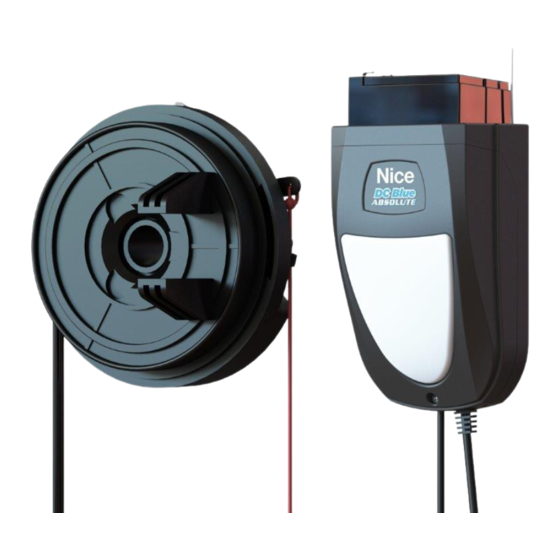
Page 5: Component Identification And Descriptions
Component identification and descriptions. Diagram Diagram Description Description number number Encoder compartment. Emergency release cord bobbin. Geared electric motor. Battery cradle. Torsion bar mounting bracket. Torroidal transformer. Motor-head chasis. Control card. Emergency release lever. Household mains supply connector with inline fuse. Drum wheel engagement fork. - Page 6 Fitting the motorhead. Open door fully. Remove open stops. Carefully feed the curtain out of the guide tracks and allow Carefully allow the door tension to unroll. Count the number the door to roll up fully. of turns as you do this. Using a rope or strap, tie the door up.
- Page 7 Slide motorhead over the torsion pole. Use a Nice drum wheel adapter plate if the fork and spoke do not fit properly. Lift door with inserted motor up onto the wall brackets. Use Check spacing and level.
- Page 8 Line up the leading edge of the curtain with the top of the Fasten the U Bolt clamps. guide tracks. Roll the door 1 to 2 times towards the wall. Not more than two turns. This should be the same as the turns removed in While holding the door firmly, remove the rope or strap.
- Page 9 Move the door through the full length of door travel to test Test the door remains stationary when closed. for snagging or coning Test the door remains stationary when left at 25% open. Test the door remains stationary when left at 50% open. Weight bar centered at bottom of door.
- Page 10 For additional support or for installations where the Pin curtain to the drumwheels, with pop rivets or “Tek” motorhead does not rest on top of the wall bracket, install a screws, in the closed position to prevent the door being “Tek”...
- Page 11 Control card wiring. Bu�on 100Ω AC AC BAT+ BAT-...
- Page 12 Using the buttons when in standby mode: (Installer actions) Trigger to run Stop the door Press release either Press release either button button Using the buttons when in programming mode: (Installer actions) Increase by 1 Decrease by 1 Select option Save value Runtime Runtime...
- Page 14 How to enter programming mode: 2 Action 3 Action 4 Confirm 5 Action 6 Confirm 1 Confirm You have entered the programming Red - A Red - A options menu. Scroll up or Green - B Green - B down to required Standby.
- Page 15 OPTION B2 - (Force) Adjusting the safety overload force sensitivity. 1 Gentle to 9 Hard (Default = 3) Confirm Action Confirm Action Confirm Confirm Red - A Red - A Red - A Green - B Green - B Green - B Program mode.
- Page 16 OPTION B5 - (Positive close) Changing the positive close level. (0 = Off, 1 = Gentle, 5 = Hard) Factory default = 1 Confirm Action Confirm Action Confirm Confirm Red - A Red - A Red - A Green - B Green - B Green - B Program mode.
- Page 17 Option A3 - Receiver: Learning a transmitter user code into the Auxiliary Relay channel. (Requires E-coms relay) Confirm Action Confirm Action Action Confirm Red - A Red - A Green - B Green - B Program mode. Press and hold 3 X Up 3 x Blinks 1 X Both to save...
-
Page 18: Troubleshooting Guide
Trigger Does not 20 x 0,5 sec 20 x 0,5 sec Repeating Repeating FET Blown • Return the control card to any Nice Group South door run at all beeps flashes 1sec on, 1 1sec on, 1 Africa (Pty) Ltd. service centre. - Page 19 Warranty. All goods manufactured by Nice Group South Africa (Pty) Ltd carry a 12 (twelve) month factory warranty from date of invoice. (In some cases a product might carry an extended warranty from time to time. Please check with Nice Group South Africa (Pty) Ltd directly or with your service/provider installer, for any extended warranty promotions that might apply to this product).
Need help?
Do you have a question about the DC Blue Absolute and is the answer not in the manual?
Questions and answers