
Related Manuals for Nice Pro-LH


Summary of Contents for Nice Pro-LH
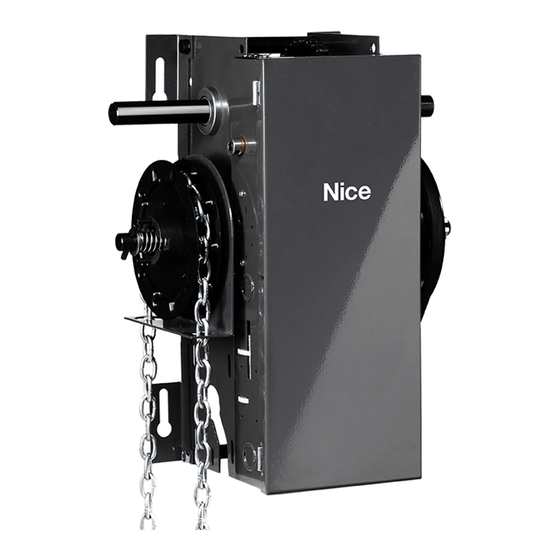
- Page 1 Pro-LH/LJ Automation for sectional and rolling doors Instructions and warnings for installation and use...
-
Page 2: Table Of Contents
Electrical Connections . . . . . . . . . . . . . . . . . . . . . . . . . . . . . . . . . . . . . . . . . . . . . . . . . . . . . . . . . . . . . . . . . . . . . . . . . . . . . . . . . . 10 SECTION A: PRO-LJ, PRO-LH Standard Relay Logic Controls (not UL325 (2010) Compliant, not available in US or Canada) . . . . . . . . . . 11 Connection of Power Supply and Control Station . -
Page 3: Warranty
Warranty NICE NORTH AMERICA warrants that materials and workmanship are free from defects for a period of four (4) years or 50,000 cycles, whichever comes first. The start of the warranty will be determined by the date of invoice. Materials returned to Nice deemed defective after examination will be returned at the option of Nice with repaired, new, or re-manufactured parts. - Page 4 PLEASE CONTACT NICE AT 1-877-888-1116 . SAVE THESE INSTRUCTIONS . Upon delivery of your Nice medium-duty jackshaft door operator, please inspect the unit carefully for damage. Verify that operator horsepower, voltage, phase and amperage correspond to available power supply and door application. Check that along with your operator you have received the following standard hardware.
-
Page 5: Pro-Lj & Pro-Lh Specifications
PRO-LJ and PRO-LH medium duty jackshaft operators are designed for commercial high lift, vertical lift, rolling doors and rolling grilles provided that doors are driven by a drive shaft with low duty cycles. Model PRO-LH is essentially the same as model PRO-LJ with the exception that the PRO-LH operator incorporates a chain hoist for manual operation of the door. -
Page 6: Important Safety Instructions
Important Safety Instructions WARNING: To reduce the risk of injury or death: • READ AND FOLLOW ALL INSTRUCTIONS • Never allow children to operate or play with door controls. Keep the remote control (where provided) away from children. • Personnel should keep away from a door in motion and keep the moving door in sight until it is completely closed or opened. NO ONE SHOULD CROSS THE PATH OF A MOVING DOOR. -
Page 7: Installation Instructions
• The PRO-LJ, PRO-LH operators have dual output shafts and may be mounted on left (standard) or right hand side of door. If handing of operator must be reversed, loosen set screws, remove drive sprocket and keyway and install on opposite side of drive shaft. - Page 8 9. Carefully re-align sprockets, if necessary and secure keyway and set screws. 10. (For the Pro-LH model) Install hand chain by wrapping it through chain guard holes and pocket wheel. Allow chain to hang down towards floor. Cut chain and connect so that chain is 2’ to 3’ from the floor.
- Page 9 11. Install chain keeper to wall near hand chain at approximately 4’ from floor. Run disconnect chain through keyhole of chain keeper and cut excess chain links if required. Attach keyring to end of disconnect chain. 12. If an optional floor level disconnect lever was ordered in lieu of the chain keeper, mount to wall with suitable hardware. Attach both chains together using keyring provided.
-
Page 10: Electrical Connections
Refer to electrical drawings inside your operator control box or generic drawings MSLLHR-WW or MSLLHR220- WW, in the electrical drawings section at the end of this manual. IMPORTANT • NICE HIGHLY RECOMMENDS THAT EACH INDIVIDUAL COMMERCIAL DOOR OPERATOR HAVE IT’S OWN DEDICATED POWER SUPPLY . • NICE HIGHLY RECOMMENDS THAT EACH INDIVIDUAL COMMERCIAL DOOR OPERATOR HAVE AN EXTERNAL CIRCUIT BREAKER OR FUSED DISCONNECT . -
Page 11: Section A: Pro-Lj, Pro-Lh Standard Relay Logic Controls (Not Ul325 (2010) Compliant, Not Available In Us Or Canada)
SECTION A: PRO-LJ, PRO-LH Standard Relay Logic Controls (not UL325 (2010) Compliant, not available in US or Canada) Connection of Power Supply and Control Station POWER WIRING: Use 1-1/8” (2.85 cm) diameter holes for all power wiring. 1. Single phase: Connect single phase power supply to terminals L/L1 (line) and N/L2 on three-pole power terminal strip. -
Page 12: Connection Of A Reversing Edge Device And Control Accessories
Connection of a Reversing Edge Device and Control Accessories 1. Reversing Edge device (must be normally open contact): NOTE: If the door is controlled by any device or wired in such a manner that the door is not controlled by constant pressure on close then an appropriate reversing edge must be installed. -
Page 13: Section B: Pro-Lj(M), Pro-Lh(M) Relay Logic Controls With Interface Module [Ul325 (2010) Compliant]
Operator Electrical Connections and Start-up Instructions NOTE: THIS OPERATOR COMES WITH AN INTERFACE MODULE INTEGRATED INTO THE CONTROL CIRCUIT. THE PURPOSE OF THE INTERFACE MODULE IS TO ALLOW FOR FAILSAFE MONITORING OF A NICE COMPATIBLE SAFETY DEVICE AS PER UL 325 (2010) REQUIREMENTS. - Page 14 3-Phase Operators: If door moves in wrong direction, turn off incoming power and reverse any two of the three incoming power supply leads to correct rotation. Press the open button and then activate the open limit to ensure door stops. If door does not stop, interchange gray and red wires on open and close limits.
-
Page 15: Select Mode Of Operation
Primary monitored safety device: Nice monitored failsafe photo beams or Nice compatible monitored failsafe devices must be connected to terminals P1 and P2 if momentary close on pushbutton is required (B2 mode). If not connected, door can only be closed by constant pressure on close pushbutton. -
Page 16: Section C: Pro-Lj(E), Pro-Lh(E) Limited Duty Smart 5 .0 Logic Board
SECTION C: PRO-LJ(E), PRO-LH(E) Limited Duty Smart 5 .0 Logic Board NOTE: The operator is shipped from the factory in the C2 mode (constant pressure close and momentary open). The operator should remain in this mode until all connections and limit switch adjustments are completed. - Page 17 Primary monitored safety device Nice monitored failsafe photo beams or Nice compatible monitored failsafe devices must be connected to terminals Pl and P2 as primary monitored safety device. Primary monitored safety device must be connected if momentary activation on close is required in B2, T and TS modes.
-
Page 18: Connection Of External Single-Button Device
4-wire electric edge: A standard 4-wire electric edge can be connected across Sl and S2 terminals as a secondary safety device. Remove the factory- installed resistor across terminals Sl and S2 when using a 4-wire electric edge. 10K OHM 4-WIRE EDGE REVERSING DEVICE... -
Page 19: Timer To Close Setup
C2 (Momentary open, constant pressure close): • Open Button: Momentary activation opens the door. When door is closing, momentary JUMPER activation reverses the door (OPEN OVERRIDE). • Close Button: Constant pressure on close. Door will stop when button is released •... -
Page 20: Section D: For All Operator Control Types
SECTION D: For all Operator Control Types Limit Switch Adjustment Adjustment of door travel is done by moving the limit cams on the threaded shaft. The position of the 4 limit switches are factory adjusted and should not be altered. The limit switches are: •... -
Page 21: Section E: For Operators With Interface Modules Or Logic Boards
For momentary activation on close, the Nice photobeams (or a Nice 2-wire monitored edge), must be installed as part of the operator system . If a Nice 2-wire monitored edge or the Nice infrared photobeam system is not installed (or not operating correctly), the operator will only operate in fault mode “constant pressure to close”... -
Page 22: Nice N-4 Photocell (Mk00650)
OPERATOR RELAY LOGIC CONTROLS OPERATOR LOGIC BOARD WITH INTERFACE MODULE NICE N-4 Photocell (MK00650) NOTE: The MK00650 photocell system has a maximum range of 24 ft. Sun visor protector optional. Installation NOTE: Photo beams should be mounted as close to the door track inside the door to offer maximum entrapment protection. -
Page 23: For Nice Nema-1 And Nema-4 Photobeams
Photo system operation: Nice photo beams must be connected for the door to close in momentary mode (unless a Nice monitored 2-wire edge is connected). When the photo system is properly installed and aligned, the infrared beam will detect any obstruction in the path of the beam. Upon detecting an obstruction, closing door will stop and reverse to full open. -
Page 24: Fraba N-4/4X Thru-Beam Photocell (Mk00697)
FRABA N-4/4X Thru-Beam Photocell (MK00697) NOTE: The MK00697 photocell system has a maximum range of 45 ft. Sun Visor protector (optional). 1. Select a location on the wall no more than 6 inches from the floor to install wall mounting brackets on the left and right side of the door. -
Page 25: Clutch Adjustment
Clutch Adjustment 1. Remove cotter pin tapped to pulley. 2. Rotate clutch nut counterclockwise (loosen) until there is insufficient tension to permit clutch to drive door. 3. Gradually tighten clutch nut until the tension on belleville washers is sufficient to permit clutch to drive door smoothly but will allow clutch to slip if door is obstructed. -
Page 26: Break Adjustment
Break Adjustment The brake adjustment is factory set and should only require minor adjustment after extensive use. Verify brake adjustment by manually holding in solenoid plunger. When brake is properly adjusted, the brake shoe pads should make complete contact with brake drum with sufficient brake spring tension to stop and maintain door when solenoid is de- energized. -
Page 27: Emergency Manual Operation
For PRO-LH operators: Operate door by pulling on hand chain. To return to electrical operation release disconnect chain and allow to return to original position. Lock hand chain in place (to Chain Keeper or Floor Level Disconnect) when not in use. -
Page 28: Operator Maintenance
Operator Maintenance WARNING TO REDUCE THE RISK OF INJURY OR DEATH: DO NOT ATTEMPT TO SERVICE THE OPERATOR UNLESS POWER SUPPLY HAS BEEN DISCONNECTED . • Inspect manual function of the door every 3-months. Make sure that door runs smoothly. If door does not manually open or close freely, have a qualified service person make repairs. -
Page 29: Jackshaft Operator Pro-Lj Parts Diagram
Jackshaft Operator Pro-LJ Parts Diagram... -
Page 30: Jackshaft Operator Pro-Lj Parts List
Jackshaft Operator Pro-LJ Parts List CODE ARTICLE# DESCRIPTION (PRO-LJ) QUANTITY MB01010 0 .5 HP Electric Motor MD00003 Sprocket 41B36 x 1" Bore 1/4" KW 2SS MD00004 Sprocket 410B12 x 1" Bore 1/4" KW (2SS 1/4"-20) MD00009 #41 Chain (45 Links C/W Link) MD00026 Sprocket 41B10 x 3/4"... - Page 31 Disconnect Lever Limited Duty MM00128 Limited Duty Frame U-Bracket Support MM00450 Limited Duty Pro-LH/LJ Frame MO00001 Cam Plate Compression Spring (0 .178ID x 0 .032G x 0 .55L) MO00006 Spring #5 0 .92"ID x 0 .09" x 2 .00" LB E .G . #5 MO00027 Clutch Spring 0 .812 ID x 0 .218 WD x 1"...
-
Page 32: Jackshaft Operator Pro-Lh Parts Diagram
Jackshaft Operator Pro-LH Parts Diagram... -
Page 33: Jackshaft Operator Pro-Lh Parts List
Jackshaft Operator Pro-LH Parts List CODE ARTICLE# DESCRIPTION (PRO-LH) QUANTITY MB01010 0 .5 HP Electric Motor MD00003 Sprocket 41B36 x 1" Bore 1/4" KW 2SS MD00004 Sprocket 410B12 x 1" Bore 1/4" KW (2SS 1/4"-20) MD00006 Sprocket 41B10 x 3/4" Bore C/W 3/16" KW 2SS... - Page 34 Limited Duty Frame U-Bracket Support MM00431 Chain Guard MM00450 Limited Duty Pro-LH/LJ Frame MO00001 Cam Plate Compression Spring (0 .178ID x 0 .032G x 0 .55L) MO00003 Pro-H/HHD Spring #4 (0 .80" ID x 0 .092" G x 1 .80" L) MO00027 Clutch Spring 0 .812 ID x 0 .218 WD x 1"...
-
Page 35: Mslhr-Ww Wiring Diagram
MSLHR-WW Wiring Diagram Nice Group Canada Inc. 1380 St Regis Blvd, Dorval, QC H9P2T5... -
Page 36: Mslh2-Ww Wiring Diagram
MSLH2-WW Wiring Diagram... -
Page 37: Ms300Lh-Ww Wiring Diagram
MS300LH-WW Wiring Diagram... -
Page 38: Mslhr-Im-Ww Wiring Diagram
MSLHR-IM-WW Wiring Diagram... -
Page 39: Mslh2-Im-Ww Wiring Diagram
MSLH2-IM-WW Wiring Diagram... -
Page 40: Ms300Lh-Im-Ww Wiring Diagram
MS300LH-IM-WW Wiring Diagram... -
Page 41: Msllhr-110V-Ww Wiring Diagram
MSLLHR-110V-WW Wiring Diagram... -
Page 42: Msllhr-220V-Ww Wiring Diagram
MSLLHR-220V-WW Wiring Diagram... -
Page 43: Notes
Notes... -
Page 44: Technical Support Hours
877-888-1116 c/o Customer Service 5919 Sea Otter Place, Suite 100 Technical Support Hours: Carlsbad, CA 92010 M – F, 8:00 a .m . – 6:00 p .m . ET Niceforyou.com ©2023 Nice North America LLC. All rights reserved. MN00067 Rev-A...
Need help?
Do you have a question about the Pro-LH and is the answer not in the manual?
Questions and answers