Table of Contents
Advertisement
Quick Links
Advertisement
Table of Contents

Related Manuals for Seikom Electronic RLSW 5A


Summary of Contents for Seikom Electronic RLSW 5A
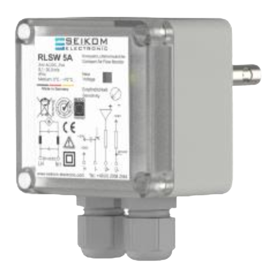
- Page 1 User Manual RLSW®5A 24 V AC/DC, 230 V AC Version 1...
- Page 2 +49 2058 916 900 0 • info@seikom-electronic.com • www.seikom-electronic.com Page: 2...
-
Page 3: Table Of Contents
User Manual RLSW®5A CONTENTS CONTENTS ..........................3 1. SAFETY INSTRUCTIONS ....................4 2. GENERAL INFORMATION ....................4 2.1 Proper Use ..........................4 2.2 Function Principle ........................4 3. TECHNICAL DATA ......................5 3.1 Dimensions ..........................6 4. INSTALLATION AND COMMISSIONING ................6 4.1 Installation Conditions ...................... -
Page 4: Safety Instructions
User Manual RLSW®5A 1. SAFETY INSTRUCTIONS Read the product description before commissioning the device. Make sure that the product is suitable for your application without any restrictions. Improper use or use not in accordance with the intended use can lead to malfunctions of the device or to undesirable effects on your application. -
Page 5: Technical Data
User Manual RLSW®5A 3. TECHNICAL DATA Type RLSW®5A Article-No. 81448/10 80448/10 Operating voltage 24 V AC/DC 230 V AC 50/60 Hz Voltage tolerance ± 5% ± 6% Overvoltage category Signal lamp voltage Green LED Power consumption 4 VA Ambient temperature -20 …... -
Page 6: Dimensions
User Manual RLSW®5A 3.1 Dimensions (Housing depth approx. 80mm) 140mm 56mm 15mm 10mm M16x1,5 Feststell- schraube 37 m m 4. INSTALLATION AND COMMISSIONING Installation and commissioning must be performed by authorized and qualified personnel. Connections to main supply (L, N) must be made by means of a protected isolating switch with usual fuses. -
Page 7: Electrical Connections
User Manual RLSW®5A ▪ In case of vertical pipes, the direction of flow should be upwards. ▪ The sensor needs at least 5xD (inside pipe diameter) of free inlet and 3xD (inside pipe diameter) of outlet path to avoid false measurement due to turbulence. ▪... -
Page 8: Commissioning Instructions
User Manual RLSW®5A 4.4 Commissioning Instructions When commissioning and adjusting the device, the following procedure is recommended: ▪ Install and connect the flow controller in accordance with installation instructions and conditions ▪ Align the mark on the end of the sensor with the air stream. ▪... - Page 9 User Manual RLSW®5A Device detects air flow when Air flow is present even at Adjust the sensor’s switching no air flow is present standstill e.g., due to point ventilation flaps through which air enters from the outside Device shows delayed Sensor tip is polluted Carefully clean the sensor reaction behavior...
-
Page 10: Eu Declaration Of Conformity
User Manual RLSW®5A 7. EU DECLARATION OF CONFORMITY +49 2058 916 900 0 • info@seikom-electronic.com • www.seikom-electronic.com Page: 10... - Page 12 Growing network of local distributors available online www.seikom-electronic.com Our Product Portfolio Flow Temperature Pressure Air Quality and CO Zener Barriers Universal Transmitters +49 2058 916 900 0 info@seikom-electronic.com www.seikom-electronic.com SEIKOM-Electronic GmbH & Co. KG Gold-Zack-Straße 7 40822 Mettmann...
Need help?
Do you have a question about the RLSW 5A and is the answer not in the manual?
Questions and answers