Table of Contents
Advertisement
Quick Links
Advertisement
Table of Contents

Related Manuals for Growatt EU SYN 400E-30


Summary of Contents for Growatt EU SYN 400E-30
- Page 1 EU SYN 400E/600E-30 User Manual...
- Page 2 Notice All products, services and features are stipulated by the contract made between Growatt and the customer. All or part of the products, services and features described in this document may not fall under the scope of purchase or usage.
-
Page 3: Table Of Contents
Table of Contents 1 Introduction ................1 1.1 Notes on this manual ................... 1 1.2 Target group ......................1 1.3 Symbol convention....................1 1.3.1 Warning signs in this manual................1 1.3.2 Symbols on the product ................... 2 2 Safety ..................3 2.1 Intended use ...................... - Page 4 7 Inspection and cleaning ............20 8 Datasheet ................21 9 Decommission ................22 9.1 Disassemble the SYN box .................. 22 9.2 Handle the SYN box................... 22 10 Contact us ................23...
-
Page 5: Introduction
1.1 Notes on this manual This manual is intended to provide product information and installation instructions for users of the EU SYN 400E-30 and EU SYN 600E-30 Automatic Transfer Switch (ATS) manufactured by Shenzhen Growatt New Energy Co., Ltd. (hereinafter referred to as Growatt). Please read this manual carefully before using the product. -
Page 6: Symbols On The Product
Symbol Description NOTICE is used to address practices not related to personal injury. NOTICE Information that you must read and know to ensure optimal system operation. Information 1.3.2 Symbols on the product Symbol Explanation High voltages! Do not touch! Risk of burns due to hot surface! Do not touch! Delayed discharge: High voltage exists after the equipment is powered off. -
Page 7: Safety
2 Safety 2.1 Intended use SYN is a dual-source automatic transfer switch. It works to automatically switch the load circuit from the main power supply (AC/GRID) to another backup power supply (GEN) when the main power supply in the commercial ESS (Energy Storage System) fails to work normally;... -
Page 8: Safety Instruction
However, certain safety precautions must be observed when installing and operating this product. Read and follow all instructions, cautions and warnings in this installation manual. Should you come into any problem, please contact Growatt's customer services at +86 755 2747 1942. -
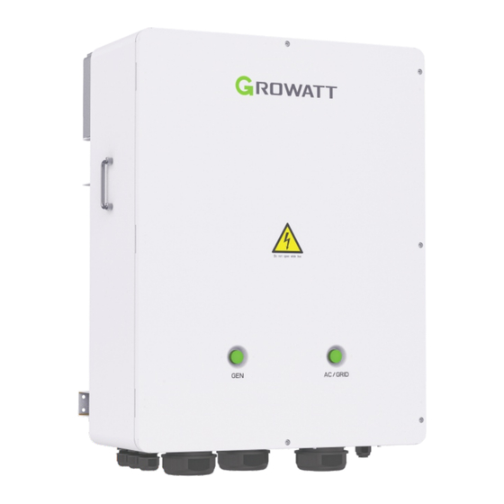
Page 9: Product Overview
3 Product overview 3.1 Appearance Fig 3.1 Designation Designation GEN indicator AC/GRID indicator Enclosure ground point Grounding terminal AC/GRID wiring terminal GEN wiring terminal LOAD wiring terminal Communication wiring terminal PE wiring waterproof cable GEN wiring waterproof cable gland gland LOAD wiring waterproof cable AC/GRID wiring waterproof cable gland... -
Page 10: Nameplate
3.2 Nameplate The diagram above shows the nameplate of EU SYN 600E-30. The nameplate is for demonstration purpose only, and the actual nameplate prevails. For other technical specifications, please refer to Section 8. -
Page 11: Dimensions
3.3 Dimensions Table 3.2 Dimensions and weight EU SYN 400E-30 Height (H) Width (W) Depth (D) Weight Without package 900mm 700mm 376mm 55kg With package 1080mm 840mm 515mm 65kg EU SYN 600E-30 Height (H) Width (W) Depth (D) Weight Without package... -
Page 12: Installation Tools
3.5 Installation tools Please prepare the following tools before installation. Fig 3.3 Installation tools Table 3.3 Tool list Name Size Name Size Flat-head Hammer Φ2&5mm screwdriver Allen key Cross-head screwdriver Φ5mm Φ5mm Electric drill Wire strippers Φ12mm Crimping Tool Wrench... -
Page 13: Unpacking
1. The EU SYN 600E-30 package includes Accessory “F” while the EU SYN 400E-30 package includes Accessory “G”. Please check the terminal specifications against the packing list. 2. Accessory “J” is only provided for the EU SYN 600E-30 model. The EU SYN 400E-30 model does not have Item “J”. -
Page 14: Installation 5
Installation 5 5.1 Basic installation requirements 1. Select a solid wall that can support the weight of the ATS. 2. Do not mount the ATS on structures constructed of flammable or heat-intolerant materials. 3. Select the installation location at eye level for the convenience of viewing and maintenance. - Page 15 Fig 5.2 Installation clearance 1. Do not install the ATS near the television antenna or any other antennas and antenna cables. 2. Ensure that the ATS is out of children's reach. 3. Though the ATS is protected to IP66, it might initiate power de-rating if exposed to direct sunlight for a long period.
-
Page 16: Installing The Wall Mount Bracket
Make sure that the ATS is installed at a proper location. Do not install it inside an enclosed space. Fig 5.4 5.2 Installing the wall mount bracket In order to avoid electrical shock or other injury, inspect existing electronic or plumbing installations before drilling holes. DANGER Drill four holes into the wall following the dimensions below: Fig 5.5... -
Page 17: Installing The Ats
1. Hammer the four expansion bolts into the holes; 2. Disassemble the nut, flat washer and spring washer of the expansion bolt; 3. Align the holes on the mounting bracket with those on the wall, then secure the bracket with the four sets of nuts, flat washers and spring washers. ①... -
Page 18: Cable Connections 6
The recommended wiring terminals are provided in the NOTICE accessory bag. If any terminal is damaged or the terminal is mismatched with the cable, please contact our after-sales services. EU SYN 400E-30 wring cables: Table 6.1 Recommended Cable type Recommended type... -
Page 19: Enclosure Grounding
6.2 Grounding the enclosure 1. Strip the insulation of the PE cable by 18 mm with a stripper. Take out the SC70-8 cable lug and insert the copper cable into it. Crimp the cord end terminal using a crimper. 2. Connect the PE cable to the ground point on the enclosure of the SYN and the system grounding bar. -
Page 20: Grounding On The Power Side
6.3.1 Grounding on the power side 1. Strip the insulation of the PE cable by 18 mm with a stripper. Take out the SC70-8 cable lug and insert the copper cable into it. Crimp the cord end terminal using a crimper. 2. -
Page 21: Connecting The Gen Power Cables
6.3.3 Connecting the GEN power cables 1. Strip the insulation layer of the power cable by 22 mm with a stripper. Take out the corresponding terminal and insert the copper cable into it. Crimp the cord end terminal using a crimper. 2. -
Page 22: Connecting The Communication Cable
Note: If you are using the plate with three cable glands, perform back-to-back cable connections on one set of the cable glands and connect the other single hole separately. 6.3.5 Connecting the communication cable 1. Strip the insulation of the communication cable by 13 mm with a stripper. Take out the red E1510-12 bootlace ferrule and insert the cable into it. -
Page 23: Sealing The Wiring Openings
6.4 Sealing the wiring openings 1. Check and ensure all cable connections are correct and secure. 2. Tighten all cable glands counterclockwise. Then seal the cable inlet openings that the power cables and communication cable thread through by applying fireproof mud evenly. Fireproof mud Fig 6.7 6.5 Securing the front cover... -
Page 24: Inspection And Cleaning 7
Inspection and cleaning 7 It is recommended to check if the GEN, AC/GRID, LOAD, PE and communication cable are damaged every three months. If any cable is damaged, please contact professional technicians for maintenance. The followings are the major maintenance items: 1. -
Page 25: Datasheet
8 Datasheet Model SYN 600E-30 SYN 400E-30 Specifications Input data (WIT) Nominal AC power 300kW 200kW Nominal AC voltage 380V/400V/415V AC grid frequency 50Hz/60Hz 600A@40℃ 380A@40℃ Max. continuous current 455A@50℃ 303A@50℃ AC grid connection type 3P4W+PE Input data (GEN) Nominal AC power 300kW 200kW Nominal AC voltage... -
Page 26: Decommission 9
Decommission 9 9.1 Disassembling the SYN box 1. Turn off all upstream switches of SYN, then wait five minutes before you open the cover. 2. Open the front cover, ensure that no residual voltage is present using a multimeter, then disconnect all cables. 3. -
Page 27: Contact Us
10 Contact us If you have technical problems concerning our products, please contact Growatt Service. To provide you with the necessary support, please have the following information ready: Ÿ SYN type Ÿ SYN serial number Ÿ Connection mode of the SYN and inverter and number of the inverter Shenzhen Growatt New Energy Co., Ltd. - Page 28 Download Manual Shenzhen Growatt New Energy Co., Ltd. 4-13/F, Building A, Sino-German (Europe) Industrial Park, Hangcheng Blvd, Bao'an District, Shenzhen, China +86 755 2747 1942 service@ginverter.com www.ginverter.com GR-UM-432-A-00 (PN:044.0134800)
Need help?
Do you have a question about the EU SYN 400E-30 and is the answer not in the manual?
Questions and answers