Advertisement
Quick Links
Advertisement

Related Manuals for Omni Micro


Summary of Contents for Omni Micro
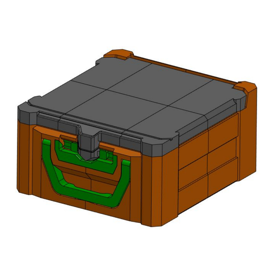
- Page 1 OMNI Micro Main Assembly...
- Page 2 Bottom Subassembly STEP 1 : Take B1_A Piece and Insert #8 Nut as shown below Insert the #8 Nut In this pocket B1_A Insert the #8 Nut In this pocket...
- Page 3 Bottom Subassembly STEP 2 : Take B2_A Piece and Insert #8 Nut as shown below Insert the #8 Nut B2_A In this pocket Insert the #8 Nut In this pocket...
- Page 4 Bottom Subassembly STEP 3 : Connect B1_A, B2_A and Lock_Plate pieces using the #8-32 x 0.5in Screw Lock_Plate B1_A B1_B Insert the #8-32 x 0.5in Screw here...
- Page 5 Bottom Subassembly STEP 4 : Take B3_A Piece and Insert #8 Nut as shown below Insert the #8 Nut In this pocket Insert the #8 Nut In these pocket B3_A Insert the #8 Nut In this pocket...
- Page 6 Bottom Subassembly STEP 5 : Take B4_A Piece and Insert #8 Nut as shown below Insert the #8 Nut In these pockets B4_A Insert the #8 Nut In this pocket Insert the #8 Nut In this pocket...
- Page 7 Bottom Subassembly STEP 6 : Place Prepared Parts together B4_A B1_A B3_A B2_A...
- Page 8 Bottom Subassembly STEP 7 : connect pieces together B4_A Insert the #8-32 x 0.5in Screw here, and also on other side B1_A B3_A Centre_Lock Plate_3 QTY Insert the #8-32 x 0.5in Screw here on all four locations B2_A...
- Page 9 Bottom Subassembly STEP 8 : Prepare the “Handle Plate” Insert the #8 Nut In these pocket and glue it there...
- Page 10 Bottom Subassembly STEP 9 : Insert the “Handle” and place the Dowel pins Place the Handle at this position Insert Dia 5 x 50mm Length Dowel Pins passing On Currently Prepared Assembly through Handle on both sides...
- Page 11 Bottom Subassembly STEP 10 : Insert and Screw the “Handle Plate” Insert the #8-32 x 0.5in Screw...
- Page 12 STEP 11 : Connect Slider Assembly Insert the Slider Assembly in pocket and connect it using #8-32 x 0.5in Screws Bottom Subassembly...
- Page 13 Top Subassembly STEP 12 : Take Top-4, Top-5, Top-6 Parts and assemble them together Insert the #8 Nut In these pockets and connect pieces using #8-32 x 0.5in Screws Insert the #8 Nut In these pockets and connect pieces using #8-32 x 0.5in Screws...
- Page 14 Top Subassembly STEP 13 : Take Top-1, Top-2, Top-3 Parts and assemble them together Insert the #8 Nut In these pockets and connect pieces using #8-32 x 0.5in Screws...
- Page 15 Top Subassembly STEP 14 : Assemble all parts together as shown here Insert the #8 Nut In these pockets Opposite side too...
- Page 16 Top Subassembly STEP 15 : Assemble all parts together as shown here Insert the #8-32 x 0.5in Screw here...
- Page 17 Top Subassembly STEP 16 : Assemble all parts together as shown here Center_Lock_Plate Use #8-32 x 0.5in to assemble Center_Lock_Plate with Other parts...
- Page 18 Top Subassembly STEP 17 : Insert Dia 15x 3 Magnet on Top Sub Assembly Insert Dia 15 x 3 Magnet on Top Part...
- Page 19 Main Assembly STEP 18 : Place Top Sub Assembly on Bottom Sub Assembly...
- Page 20 Main Assembly STEP 19 : Insert Dia 5 x 50mm Dowel Pins Insert Dia 5 x 50mm Dowel Pin in this pocket and Slide to left...
- Page 21 Main Assembly STEP 20 : Insert Dia 5 x 50mm Dowel Pins Again Insert Dia 5 x 50mm Dowel Pin in this pocket and Slide to right...
- Page 22 Main Assembly STEP 21 : Insert Dia 5 x 50mm Dowel Pins Insert Dia 5 x 50mm Dowel Pin in this pocket and Slide to left...
- Page 23 Main Assembly STEP 22 : Insert Dia 5 x 50mm Dowel Pins Insert Dia 5 x 50mm Dowel Pin in this pocket and Slide to right...
-
Page 24: Lock In Place
LOCK IN PLACE Lead comes down... - Page 25 OMNI Micro Main Assembly...
Need help?
Do you have a question about the Micro and is the answer not in the manual?
Questions and answers