
Related Manuals for Renogy REGO RIV1230RCH-24S


Summary of Contents for Renogy REGO RIV1230RCH-24S
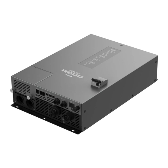
- Page 1 REGO HF Inverter Charger 3000W VERSION A0 RIV1230RCH-24S June 8, 2024 USER MANUAL...
- Page 2 The illustrations in the user manual are for demonstration purposes only. Details may appear slightly different depending on product revision and market region. z Renogy reserves the right to change the information in the user manual without notice. For the latest user manual, visit renogy.com.
-
Page 3: Table Of Contents
Table of Contents General Information ........................... 1 1.1. Symbols Used .............................. 1 1.2. Qualified Personnel............................. 1 1.3. Introduction ..............................1 1.4. Key Features ..............................1 1.5. SKU ................................2 Get to Know REGO 12V 3000W HF Inverter Charger ............... 3 2.1. - Page 4 10.2. Technical Specifications .........................46 11. Maintenance ............................. 48 11.1. Inspection ..............................48 11.2. Cleaning ..............................48 11.3. Storage ...............................48 12. Emergency Responses ........................49 12.1. Fire ................................49 12.2. Flooding ..............................49 12.3. Smell ................................49 12.4. Noise ................................49 Renogy Support ............................50...
-
Page 5: General Information
The inverter charger can be connected to Renogy devices and smart accessories via Bluetooth or RV- C. When the inverter charger works in association with the DC Home app or Renogy ONE, you will have the same system monitoring wherever you go on your smartphone. With advanced pure sine wave technology, the inverter charger can protect and extend the life of your electronic equipment and loads. -
Page 6: Sku
z Automatic generator start Equipped with dry contacts for automatic generator start and stop function, facilitating battery charging. z Multiple protections Provides undervoltage, overvoltage, overcurrent, overload, overtemperature, and short circuit protections for enhanced safety. 1.5. SKU REGO 12V 3000W HF Inverter Charger RIV1230RCH-24S —... -
Page 7: Get To Know Rego 12V 3000W Hf Inverter Charger
Get to Know REGO 12V 3000W HF Inverter Charger 2.1. What’s In the Box? REGO 12V 3000W HF Inverter Charger × 1 REGO HF Inverter Charger 3000W RIV1230RCH-24S VERSION A0 June 8, 2024 ST6.3*1.8*13 mm USER MANUAL User Manual × 1 Self-tapping Screws x 8 (2 extra) AC Input Connector x 1... -
Page 8: Product Overview
2.3. Product Overview Wired Remote (REMOTE) Port CAN1 Ports (Reserved) CAN2 Communication Ports Bluetooth Antenna Cover On/Off/Remote Battery Positive Port (M8 Terminal) Power Switch AC Output Port Mounting Holes Battery Negative Port (M8 Terminal) Ground Port (M4) Battery Temperature Sensor (BTS) Port AC Input Port Dry Contact (DRED) Port Battery Voltage Sensor (BVS) Port... -
Page 9: System Setup
2.4. System Setup Positive (DC) Negative (DC) Ground Communication Remote control AC Loads (240V) Grid Power (240V) AC Load Sub-panel ANL Fuse (400A) RMS-P2 Wired Remote Battery System Grounding RV-C or REGO Control (12V) Series Devices The wiring diagram only shows the key components in a typical DC-coupled off-grid energy storage system for the illustrative purpose. -
Page 10: Preparation
Preparation 3.1. Plan a Mounting Site The inverter charger requires adequate clearance for installation, wiring and ventilation. The minimum clearance is provided below. Ventilation is highly recommended if it is mounted in an enclosure. Select a proper mounting site to ensure the inverter charger can be safely connected to the battery and grid/AC generator with the relevant cables. -
Page 11: Check The Inverter Charger
Ensure the inverter charger is firmly grounded to a building, vehicle, or earth grounded. Keep the inverter charger away from EMI receptors such as TVs, radios, and other audio/visual electronics to prevent damage / interference to the equipment. To ensure good ventilation and optimal system performance, It is prohibited to invert (terminals up) the inverter charger and block the cooling fans. -
Page 12: Check The Battery
(4/0 AWG / 107 mm2) × 2 (4/0 AWG / 107 mm2) Components and accessories marked with “*” are available on renogy.com. 1. Inspect the battery for any visible damage including cracks, dents, deformation, and other visible abnormalities. All terminals shall be clean, free of dirt and corrosion, and dry. - Page 13 During the charging process, the battery must be placed in a well-ventilated place. Do not use the battery if there is any visible damage. Do not touch the exposed electrolyte or powder if the battery housing is damaged. When being charged, the battery may give off explosive gas. Make sure there is good ventilation. Take care to use a high-capacity lead-acid battery.
-
Page 14: Check The Ac Loads (Appliances)
4. Inspect the Battery Adapter Cables for any visible damage including cracks, dents, deformation, and other visible abnormalities. All ring terminals are fastened to the cables. Do not use the battery adapter cables if there is any visible damage. 3.4. Check the AC Loads (Appliances) Recommended Components &... -
Page 15: Check The Ac Generator Or The Grid (Optional)
3.5. Check the AC Generator or the Grid (Optional) Recommended Components & Accessories Recommended Cable Size 0.36 in Cable Length Cable Size (9 mm) 0 ft to 10 ft 9 AWG (6.6 mm²) 9 to 7 AWG 11 ft to 20 ft (6.6 mm²... - Page 16 2. Remove the terminal plugs AC Input Connector AC Output Connector from the housings for both the connectors. 3. Loosen the locking nuts from AC Input Connector AC Output Connector the terminal plugs by twisting them clockwise. 4. Run the three wires (live, AC Input Connector AC Output Connector neutral, and ground) through...
- Page 17 6. Use the included inner hexagon AC Input Connector AC Output Connector spanner to rotate the cable retainers of the L, N, and PE terminals on the AC connectors counterclockwise. Ensure the cable retainer is completely open. Open Closed Open Closed 7.
-
Page 18: How To Properly Unplug Ac Input/Output Connectors
10. Rotate the locking nuts AC Input Connector AC Output Connector counterclockwise to tighten them until they cannot be turned further. 3.7. How to Properly Unplug AC Input/Output Connectors? As shown in the illustration, use a 1 mm slotted screwdriver to press down on the latch on an AC connector. -
Page 19: Installation
Installation To ensure safe and efficient operation of the inverter charger and to avoid potential damage or hazards, always follow the installation instructions in the sequence described in this manual. 4.1. Wear Insulating Gloves Insulating Gloves 4.2. Installing Mounting Plates Install the mounting plates to the rear of the inverter charger using the included grub screws and a #1 Phillips screwdriver. -
Page 20: Ground The Inverter Charger
Make sure that the inverter charger is installed firmly to prevent it from falling off. 4.4. Ground the Inverter Charger Recommended Components 3/16 in (M4) Grounding Cable (9 AWG / 6.6 mm²) Step 1: Remove the screw on the Ground Port with a Phillips screwdriver (#1). Step 2: Connect the Grounding Cable Ring Terminal to the grounding port of the inverter charger with the removed screw by using the Phillips screwdriver (#1). -
Page 21: Connect The Inverter Charger To A Battery
Step 4: Connect the Positive Ring Terminal of the Battery Adapter Cable (in red) and MRBF Terminal Fuse to the Positive Busbar on the Renogy 500A Combiner Box. The retaining nut torque of the Battery Positive/Negative Terminal is 70.8 in·lbs (8 N·m). Do not overtighten it to prevent damage. - Page 22 █ Battery Scenario B: Normal Battery Kit Step 1: Remove the retaining nut from the Battery Negative Terminal on the inverter charger by using a Socket Wrench. Run the Negative Battery Adapter Cable through the grommet of the Battery Negative Port of the inverter charger, and connect the ring terminal of the Negative Battery Adapter Cable to the Battery Negative Terminal with the retaining nut.
-
Page 23: Install The Cover
Recommended Components *Battery Temperature Sensor Components marked with “*” are available on renogy.com. Do not use the temperature sensor on a LiFePO4 (LFP) battery which comes with a battery management system (BMS). -
Page 24: Install A Battery Voltage Sensor (Optional)
Recommended Components *Battery Voltage Sensor Components marked with “*” are available on renogy.com. █ Battery Scenario A: REGO Battery Kit Step 1: Connect the terminal block to the Battery Voltage Sensor (BVS) Port on the inverter charger. Step 2: Connect the Negative Ring Terminal of the Battery Voltage Sensor to the Negative Busbar on the Renogy 500A Combiner Box. - Page 25 █ Battery Scenario B: Normal Battery Kit Step 1: Connect the terminal block to the Battery Voltage Sensor (BVS) Port on the inverter charger. Step 2: Connect the Negative Ring Terminal of the Battery Voltage Sensor to the Negative Terminal on the 12V battery.
-
Page 26: Install A Wired Remote Control (Optional)
RMS-P2 *Wired Remote Control Components marked with “*” are available on renogy.com. Step 1: Connect the RJ12 connector to the Wired Remote (REMOTE) Port on the inverter charger. Step 2: Connect the other end of the cable to the Wired Remote Control. - Page 27 Bare Wires AC Loads (240V) — 23 —...
-
Page 28: Connect The Inverter Charger To The Grid
4.12. Connect the Inverter Charger to the Grid (Optional) Step 1: Align the latch of the wired AC Input Connector with the slot on the AC Input Port of the inverter charger, and insert the connector vertically to the base. Step 2: Locate the live, neutral, and ground terminals on the grid, and connect the bare wires of the AC Input Connector to the respective terminals on the grid. -
Page 29: Can Communication Wiring (Optional)
Generator 4.13. CAN Communication Wiring (Optional) The REGO 12V 3000W HF Inverter Charger can communicate with other Renogy devices supporting CAN communication and monitoring devices through CAN (common area network) bus, also known as RV-C, enabling safe operation, smart control, remote monitoring, and programmable settings. - Page 30 Ensure 120 Ω terminating resistors are installed at both ends of the RV-C bus for successful communication with Renogy devices supporting CAN communication. If the RV user manual does not determine if the RV-C bus has a built-in 120 Ω termination resistor, call the RV manufacturer to confirm.
- Page 31 The drop taps are usually located above the entry door, in the bathroom, or under the bed in the RV. Step 4: Connect the Drop Plugs on the drop cables and other Renogy devices supporting CAN communication to the drop sockets on the drop tap.
- Page 32 RJ45 Port Adapter Cable(s) RJ45 Communication Cable(s) Terminal Plug Accessories marked with “*” are available on renogy.com. The communication cable should be less than 19.6 feet (6 m). Choose proper terminal plugs based on the specific CAN ports. The quantity of adapter cables and plugs varies based on the position of the inverter charger in the daisy chain network.
-
Page 33: Inspection
4.14. Inspection Check and confirm all wires are firmly fastened to the inverter charger. — 29 —... -
Page 34: Power On/Off And Led Indicators
Power On/Off and LED Indicators 5.1. Power On/Off █ Method 1: Through On/Off/Remote Power Switch OFF: The inverter charger is off. The inverter charger uses grid power to directly power AC loads or appliances without drawing power from the batteries. The grid charges the connected battery at the same time. -
Page 35: Led Indicators
5.2. LED Indicators A solid yellow or red LED indicates that the inverter charger is faulty. Please login to the DC Home app for troubleshooting details. █ Indicator of the Inverter Charger AC INPUT LED Indicator Off: No AC input detected Solid: The grid voltage is normal Flash: The grid is supplying the... -
Page 36: Configuration
Configuration 6.1. N-G Bonding Relay The inverter charger is equipped with a Neutral to Ground (N-G) bonding relay that ensures that either the neutral in or out contact of the RV is always grounded. This helps prevent electrical shock caused by contact between the neutral contacts of the RV and external AC power sources. -
Page 37: Residual Current Device (Rcd)
Simply flip the switch upward to restore operation of the inverter charger. For technical support, contact our technical service through renogy.com/contact-us. 6.3. Configuration Panel... -
Page 38: Set A Battery Type
6.4. Set a Battery Type Upon installing the inverter charger, set a correct battery type by using the Battery Type Setting Button. Press the Battery Type Setting Button to cycle through different battery types with the LED indicator illuminating in respective colors. It is essential to ensure that the battery type is configured correctly to avoid any potential damage to the inverter charger because any damage to the inverter charger resulting from an incorrect battery type setting voids the warranty. - Page 39 Read the user manual of the battery when customizing a preset battery. Incorrect battery type selection damages the inverter charger and voids the warranty. Battery Type USER USER SLD/AGM FLOODED LI (LFP) (Default) (Recommended) Parameters Overvoltage 15.8V 15.8V 15.8V 15.8V 15.8V 9.0—16.0V Shutdowm...
-
Page 40: Set An Ac Output Frequency
1. For lead-acid batteries, please consult your battery manufacturer to obtain the voltage value and then complete the settings according to the feedback. Equalization Voltage 2. If equalization charging is not required, set the voltage to boost voltage. This value affects whether the battery can be fully charged. Please Boost Voltage consult the battery manufacturer and set the value properly. -
Page 41: Monitor The Inverter Charger
Step 1: Open the DC Home app. Tap + to search for new devices. Step 2: Tap Confirm to add the newly found device to the device list. Step 3: Tap the inverter charger icon to enter the device information interface. My Renogy My Renogy HUB Mode... -
Page 42: Wireless Long-Range Monitoring
7.2. Wireless Long-Range Monitoring If long-range communication and programming are required, connect the inverter charger to Renogy ONE (sold separately) through Bluetooth, and the Renogy ONE to the DC Home app through Wi-Fi. Recommended Components *RENOGY ONE Core Components marked with “*” are available on renogy.com. -
Page 43: Wired Long-Range Monitoring (Daisy Chain Network)
Common Drop Tap following the terminal block plug pinout. Plug the Drop Cable to the RJ45 port of Renogy ONE. Step 2: Monitor and program the complete system on Renogy ONE or the DC Home app. Internet My Renogy... - Page 44 Step 1: Remove the Terminator Plug from the Renogy device at either end of the daisy chain. Step 2: Connect the Renogy ONE to the free CAN Communication Port on the Renogy device with the Communication Adapter Cable (sold separately) and RJ45 Ethernet Cable.
-
Page 45: Working Logic
Working Logic REGO 12V 3000W HF Inverter Charger combines an inverter charger with an automatic transfer switch into one complete system. Featuring a three-stage battery charging mode when connected to the AC grid input, the inverter charger is capable of producing cleaner, smoother, and more reliable electricity to address your diverse needs. -
Page 46: Charging Logic
█ Supply by Both Battery and AC Battery AC Loads Grid Power The inverter charger uses both battery and grid as the supply when all of the following conditions are met: z Neither the battery nor the grid can independently supply all loads. z The battery voltage is no lower than the Low Voltage Shutdown value. -
Page 47: Battery Charging Stages
z For lithium batteries: The battery charging is considered complete when the battery stays in the constant voltage charging stage with a charging current less than the battery tail current for 2 hours. 8.3. Battery Charging Stages Reset to Bulk Bulk Float Charge... -
Page 48: Heat Dissipation Logic
8.4. Heat Dissipation Logic The inverter charger uses fans for heat dissipation. The working logic of the fans is as follows: Inverter Charger Inverter Charger Power Inlet air temperature ≥86°F (30°C) — Internal temperature ≥104°F (40°C) — — ≥ 200W The fans start working when any of the above condition is met. -
Page 49: Troubleshooting
3. Keep the phone or tablet within 10 feet (3 tablet where the DC Home m) of the inverter charger. app runs. For technical support, contact our technical service through renogy.com/contact-us. — 45 —... -
Page 50: Dimensions & Specifications
10. Dimensions & Specifications 10.1. Dimensions 0.28 in (7 mm) 18.66 in (474 mm) 0.28 in (7 mm) 12.13 in (308 mm) 4.29 in (109 mm) 1.18 in 1.18 in (30 mm) (30 mm) Dimension tolerance: ±0.2 in (0.5 mm) 10.2. - Page 51 Output Frequency 50Hz (±0.1Hz) (Default) / 60Hz (±0.1Hz) Output Wave Form Pure Sine Wave Nominal Input Voltage 12V DC Input Voltage Range 9V to 17V DC (±0.3V) (Full load 11V to 15.8V DC) Short Circuit Protection Software Protection Total Harmonics Distortion (THD) <...
-
Page 52: Maintenance
11. Maintenance 11.1. Inspection For optimum performance, it is recommended to perform these tasks regularly. z Ensure the inverter charger is installed in a clean, dry, and ventilated area. z Ensure there is no damage or wear on the cables. z Ensure the firmness of the connectors and check if there are any loose, damaged or burnt connections. -
Page 53: Emergency Responses
2. Make sure no foreign objects are stuck in the fan of the inverter charger or the ring terminal. The normal noise value of the inverter charger is less than 54dB during operation. If the noise is abnormal, contact our technical service through renogy.com/contact-us. — 49 —... -
Page 54: Renogy Support
Questionnaire Investigation To explore more possibilities of solar systems, visit Renogy Learning Center at: renogy.com/learning-center For technical questions about your product in the U.S., contact the Renogy technical support team through: renogy.com/contact-us 1(909)2877111 For technical support outside the U.S., visit the local website below: Canada ca.renogy.com... - Page 55 FCC Statement This device complies with Part 15 of the FCC Rules. Operation is subject to the following two conditions: (1) This device may not cause harmful interference. (2) This device must accept any interference received, including interference that may cause undesired operation.
- Page 56 Save 105 gallons of water from being consumed Renogy Power PLUS Renogy Power Plus allows you to stay in the loop with upcoming solar energy innovations, share your experiences with your solar energy journey, and connect with like-minded people who are changing the world in the Renogy Power Plus community.
Need help?
Do you have a question about the REGO RIV1230RCH-24S and is the answer not in the manual?
Questions and answers