
Related Manuals for Dyness DH100F


Summary of Contents for Dyness DH100F
- Page 1 DH100F DH100F ESS+PV Cabinet User manual Version:202405-V1.0-EN, the version is subject to update without notice...
-
Page 2: Table Of Contents
DH100F Content Statement of Law .............................1 Revised History ..............................1 1. Guideline ............................... 2 1.1. Use of manuals ..........................2 1.2. Applicable products ........................2 1.3. Product profile ..........................3 1.4. Symbol and abbreviation ......................3 2. Safety Instructions ............................. 5 2.1. Safety Principle ..........................5 2.2. - Page 3 DH100F 5.6. Checking Before Wiring ......................34 5.7. Pe Wiring ............................35 5.8. Electrical Wiring ...........................36 5.9. Communication Wiring ......................40 5.10. Meter Installation ........................41 5.11. Checking After Wiring ......................43 6. Power on and power off ........................44 6.1. Power On Process ........................44 6.2.
-
Page 4: Statement Of Law
DH100F Statement of Law The copyright of this document belongs to Dyness Digital Energy Technology Co.,LTD. (the following will be referred to as "Dyness"). No part of this document may be excerpted, translated, annotated or reproduced in any form or by any means without the prior written authorization of Dyness. -
Page 5: Guideline
ESS product, as well as users who carry out daily operation. Readers should have certain electrical knowledge. 1.2. Applicable products This manual applies to outdoor air-cooling ESS products (DH100F) of Enercore series.The definition are explained as below: DH: Dyness high voltage series products;... -
Page 6: Product Profile
DH100F 1.3. Product profile Function introduction: this product is an outdoor air cooling ESS cabinet which integrates Pack, BDU(include BMS and DC power distribution), DC/DC, MPPT, Distribution module(include EMS and AC power distribution), fire protection system, air conditioner system and so on. This product can provide users with services like peak-shaving, capacity and demand reduction, capacity expansion, demand response and so on. - Page 7 DH100F Energy Management System Battery Management System Battery Distribution Unit Surge protection device State of Charge State of Health Direct Current Alternating Current Photovoltaic MPPT Maximum Power Point Tracking Thermo Magnetic Generator Residual Current Device Current Transformer Protective Earthing...
-
Page 8: Safety Instructions
DH100F 2. Safety Instructions 2.1. Safety Principle Related safety precautions need to be strictly followed during installation, operation and maintenance. This product is a combined high-voltage DC and three-phase AC system and should only be operated by authorized personnel. DANGER ... -
Page 9: Environmental Safety Requirements
DH100F 2.3. Environmental Safety Requirements Do not install and use the product in environments with temperature below -20°C or above 50°C; Do not install and use the product near any heat sources or combustible materials; Do not install and use the product in areas with frequent movement of personnel;... -
Page 10: Transportation And Installation Safety Requirements
The operating manual of the measuring device must be known before any measurement is carried out; Only use equipment specified by Dyness. Failure to use equipment specified by Dyness may result in impaired protection as well as injury to personnel. -
Page 11: Product Obsolescence
DH100F Dyness authorization. If changed, the corresponding liability and warranty shall be void. Do not remove or alter the nameplate; Do not open the cabinet doors in inclement weather such as rain or strong winds; 2.7. Product Obsolescence When the product as a whole or individual internal components become aged or damaged and need to be discarded, they cannot be disposed as regular waste. -
Page 12: Product Description
DH100F 3. Product Description 3.1. Product System Overview The product is an outdoor ESS+PV all-in-one cabinet, which could provide users with peak-shaving, capacity and demand reduction, capacity expansion, demand response and other functions. It can be widely used in charging stations, commercial buildings, manufacturing industry and other small industrial and commercial scenarios. -
Page 13: System Composition
Air conditioner Adjust battery working temperature to ensure it standard system works under optimal temperature. The users could choose the number of MPPT module and Packs as demand, Dyness provide the following configurations: Table 3-2 Product model and configuration Model Description... -
Page 14: System Parameters
PV+ESS, 1 MPPT (expandable); DH100F-S01L01C100 7pcs System capacity: 100kWh DH100F-S02L01C100 PV+ESS, 2 MPPT; System capacity: 100kWh 7pcs 3.3. System Parameters DH100F parameters is shown as follows (the parameter may vary without notice during product upgrade). Table 3-3 ESS Parameter Model DH100F-71kWh DH100F-86kWh DH100F-100kWh Battery system specification parameters:... - Page 15 DH100F AC specification parameters (off-grid): Rated power 35kVA 40kVA 50kV Max. AC current AC rated voltage 400Vac Wiring method 3P+N+PE Frequency 50Hz/60Hz Unbalanced load 100% THDv@Liner Load <3% PV access Max. input power 25kW*2 30kW*2 35kW*2 Max. current 80A *2 Max.Short-circuit current...
-
Page 16: System Expansion
DH100F 3.4. System Expansion The product support DC expansion and AC expansion to satisfy the greater capacity needs of customers. DC Expansion The product is reserved DC expansion interface on the copper bar at the rear electrical compartment for accommodating future battery expansion, which effectively solve the battery inconsistency issue and could support mix-use of new and old batteries. -
Page 17: Appearance Design
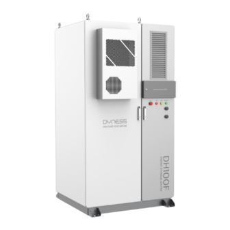
DH100F 3.5. Appearance Design Dimension: 1200*1048*2258mm (fixed basement not included); Net weight: Approx. 1610kg (model DH100F-S02L01C100 as reference); Product IP grade: IP55; Anti-corrosion level: C3. Front Left Back Right Figure 3-4 Product appearance The product is equipped with an HMI screen on the front panel, with a baffle for... - Page 18 DH100F the running status of the product: emergency stop button”EPO”, alarm indicator”FAULT”, running indicator”RUN” and power indicator”POWER”. HMI screen baffle Running indicator Alarm indicator Power indicator Figure 3-5 Product indicators Table 3-4 Indicator name and function Color Name Function ●...
-
Page 19: Internal Design
DH100F 3.6. Internal Design The product consist of two parts: battery compartment and electrical compartment. Battery compartment: Pack, BDU (incorporating DC power distribution and BMS), air conditioner, fire protection system and access control system; Electrical compartment: MPPT, PCS, DC/DC, power distribution module (AC power... - Page 20 Please use gauze (ordinary medical gauze) or other liquid absorbent solids to clean the battery leakage; The treated battery should be placed in isolation and should not be used again. The above operations shall be completed by personnel designated by Dyness or qualified professionals.
- Page 21 DH100F 3.7.2. PCS PCS function: PCS is bi-directional current-controllable device that connect the grid and ESS. Its main function is to facilitate energy exchange between the battery and grid, as well as control and manage charging/discharging of the battery. It enables...
- Page 22 DH100F 3.7.4. MPPT MPPT function: supporting MPPT mode to enhance the efficiency of PV panels or supplying power to Loads via AC/DC. Protection functions: over-current protection, over-temperature protection, under- voltage protection on the low-voltage side/ high-voltage side, over-power protection, short-circuit protection on the low-voltage side, and reverse connection protection.
- Page 23 DH100F 3.7.6. Distribution Module The distribution module includes AC circuit breaker, contactor, PV breaker, meter, SPD and EMS, etc. Figure 3-12 Distribution module (image only for reference) EMS is an essential part of ESS. It communicate with PCS, BMS, meter, fire protection system, air conditioner and other devices to control the whole ESS.
- Page 24 DH100F 3.7.7. Security System Fire Protection System: The product is equipped with a composite detector (smoke/ temperature/ gas detector) and fire extinguishing agent on the top of the battery compartment. When any of the three built-in detectors detects an anomaly, the system will stop operating and report the anomaly.
-
Page 25: Transportation And Storage
Carefully check whether the product is in good condition, the transportation process may lead to damage due to transportation collision, if any problem is found, please contact Dyness or the transportation company in time. Shipping Requirement All necessary equipment in the product have been installed and fixed in the cabinet before leaving the factory, and the product can be transported as a whole during transportation. -
Page 26: Forklift Transportation
DH100F Ensure that all sling connections are safe and reliable, and ensure that each section of the sling connected to the corner piece is of equal length; The length of the slings can be adjusted appropriately according to the actual requirements of the site;... -
Page 27: Storage Requirement
DH100F √ √ Correct shipping method: False shipping method: Figure 4-2 Forklift Transportation 4.4. Storage Requirement Storage Environment Requirements: The product should be stored on dry, flat ( flatness should be no more than 5mm), solid ground with sufficient load-bearing capacity and without any vegetation cover;... -
Page 28: Installation
DH100F 5. Installation Only a qualified electrical engineer can operate related electrical connection. Please comply with the requirements given in "Safety Instructions" in chapter 2 and we shall not be liable for casualties or property loss caused by neglect of safety instructions. -
Page 29: Installation Environmental Requirements
DH100F 5.1. Installation Environmental Requirements Site Requirements When selecting the installation site, full consideration should be given to the surrounding environment (climate and geological conditions, such as stress wave emission, underground water level, no high cables in the vertical upper part of the... -
Page 30: Installation Spatial Requirements
DH100F 5.2. Installation Spatial Requirements The product adopts front-rear ventilation. Make sure that the equipment has enough space for better cooling and maintenance, it is advised to reserve enough space around the cabinet installation position. The reserved space in front of a single product should not be less than 700mm. -
Page 31: Installation Procedure
DH100F 5.3. Installation Procedure Product installation please follow the below steps, The specific operation process is detailed in this chapter. ① shipping ② Check before ③ Fix angle iron ④ Open the door to the site installation (refer to 5.4) (refer to 5.4) -
Page 32: Fixed Installation
DH100F 5.4. Fixed Installation Check Before Installation WARNING Please comply with local safety regulations and operational rules during installation. Only complete and undamaged equipment can be installed! Please ensure that before installation: The product cabinet itself should be complete and intact. - Page 33 DH100F L-shaped angle iron brackets installation steps ① Use a marker pen to mark the drilling positions. ② Choose an electric drill with a diameter matching the bolt's outer diameter, drill holes according to the bolt's length (hole depth slightly greater than the bolt length) until reaching the desired depth for installation.
-
Page 34: Preparation Before Installation
DH100F 5.5. Preparation Before Installation 5.5.1. Wiring Tools Insulated Gloves Safety Goggles Safety Shoes Protective suit Figure 5-7 Safety gear Phillips Screwdriver Bit Wire stripper Crimping Hair Dryer Multimeter Flat-Head Screwdriver Wrench Drill Tape Measure Figure 5-8 Tools... - Page 35 DH100F 5.5.2. Wiring Accessories Requirements Cable Requirements: Having sufficient current-carrying capacity. The cable diameter must satisfy the maximum current-carrying capacity, and the length must allow for a margin. The specifications and materials of three-phase AC output cables should be consistent.
- Page 36 DH100F 5.5.3. Terminal Wiring Method OT/DT terminals connection step: (1) Peel off the insulation skin from the cable terminal, and the length of which should be the depth of the wire hole on the copper terminal, plus an additional 2-3mm.
-
Page 37: Checking Before Wiring
DH100F 5.6. Checking Before Wiring 1) Checking breakers Check whether the next following circuit breakers is in the disconnected position. “QF4” on the front panel of BDU (as shown in position 1); Battery breakers (“BAT”) on the front panel of BDU (as shown in position 2);... -
Page 38: Pe Wiring
DH100F 5.7. Pe Wiring The product is TN-S system, there are grid PE and load PE inside the product. For off-grid applications, RCD (Residual Current Device) need to be installed at the off- grid port, with type B being recommended. -
Page 39: Electrical Wiring
DH100F 5.8. Electrical Wiring Step 1: battery connection To ensure the safety of the product, the power cables for the batteries are shipped with the product and need to be installed on-site as follows: (1) Please reconfirm the battery switch is off (as shown in position 1);... - Page 40 DH100F Step 2: PV Connections The product that is equipped with MPPT module, it need to connect the PV cables, please skip this step without MPPT. (1) Please reconfirm the PV switches (“PV1” and “PV2”) are off (as shown in position 1), and measure with DC setting of multimeter to make sure there is no voltage;...
- Page 41 DH100F Step 3: Grid Connections (1) Please reconfirm the grid switch ( labeled “GRID” ) are off (as shown in position 1), and measure with AC setting of multimeter to make sure there is no voltage; (2) Guide the grid cables into the front electrical compartment through the inlet hole (as shown in position 2);...
- Page 42 DH100F Step 3: Load Connections (1) Please reconfirm the Load switch ( labeled “LOAD” ) are off (as shown in position 1), and measure with AC setting of multimeter to make sure there is no voltage; (2) Guide the load cables into the front electrical compartment through the inlet hole (as shown in position 2);...
-
Page 43: Communication Wiring
DH100F 5.9. Communication Wiring The EMS is incorporated inside distribution module; Be sure to use correct communication cables ( 16AWG recommended); The product is adjustable to multiple protocol, it has multiple external communication ports: LAN, USB, CAN, 4G, GPS, SD, SIM card, shown as follows:... -
Page 44: Meter Installation
IA, IB, IC on the meter. The current connections are as follows: Ta(S1),Ia Ta(S2) Tb(S1),Ib Tb(S2) Tc(S1),Ic Tc(S2) (4) External transformers must be grounded; (5) The meter communicate with DH100F through RS485, connect the meter to the port labeled ”3A/3B” of COM6 on the distribution module. - Page 45 DH100F Primary meter Distribution module Current transformer Figure 5-17 Primary meter installation Distribution module Current transformer Secondary meter Figure 5-18 Secondary meter installation Notice: DTSD1352 is equipped with mA level transformer, it is strictly prohibited to access to 5A or 1A output transformer, which may damage the meter;...
-
Page 46: Checking After Wiring
DH100F (2) Meter Debugging: The meter debugging can only be set after power on. Product power on please refer to 6.1. (1) Set current ratio: , the current ratio is set based on actual conditions, e.g. if the ratio is 200:5, set it to 0040. -
Page 47: Power On And Power Off
DH100F 6. Power on and power off 6.1. Power On Process Precautions: The product can only be put into operation after being confirmed by professionals and approved by the local power department. For products with a long shutdown time, before powering on, a comprehensive and detailed inspection must be carried out on the equipment to ensure that all indicators meet the requirements before powering on. -
Page 48: Power Off Process
DH100F Step 3: Close “GRID” switch; Step 4: Close “LOAD” switch; Step 5: Close “QF1”, “QF2” ,“QF3” switches; Step 4 Step 5 Step 3 Figure 6-2 Distribution module front panel operation Step 6: Close PV breakers (“PV1/PV2”), skip this step if no MPPT. -
Page 49: Emergency Stop
DH100F Step 6: disconnect “QF4” ; Step 7: disconnect BAT” switch; WARNING After operating step by step, the system will stop running, and the product indicators and screen will go out. After the inspection is completed, wait for five minutes to perform maintenance and inspection operations. -
Page 50: Hmi Operation
System only accepts commands from external EMS which could control the system through the EMS of this product. 7.1.2.Automatic mode The system EMS accept command from the system HMI and Dyness cloud platform to execute the following modes. Anti-backflow function For application where PV is not allowed to feed the grid, EMS will control PV output supply the load first, and store excess PV energy to ESS. -
Page 51: Operation System Overview
DH100F 7.2. Operation System Overview The product is equipped with 7-inch screen, on where the users could check the system information ad set system parameters. Table 7-1 HMI interface overview Main Main menu Level 1 Level 2 Level 3 window... -
Page 52: User Login
DH100F HMI main interface Language setting: At the upper right of main interface, user could select display language; Dashboard: display the details of system access device; Data: query the detailed data, alarm information, version information of each sub- ... - Page 53 DH100F Figure 7-2 General user login step Change password Step 1: Click “Modify” at the upper left of navigation bar; Step 2: Input old password and new password, complete the setting, then click “Confirm modification”; -- END Figure 7-3 Change password diagram (image only for reference)
-
Page 54: Running Information
DH100F 7.4. Running information Method 1:click corresponding icons on the main interface and directly enter corresponding module data interface; Click Grid icon , enter Grid interface; Click load icon , enter Load interface; Click ACDC icon , enter ACDC interface;... -
Page 55: Query Data
DH100F 7.5. Query data Step 1: Click main menu icon on the upper right corner of the main interface; Step 2: Click “Data” under main menu bar; Step 3: Select corresponding sub-menu (EMS/ ACDC / DCDC/ MPPT /BMS data / Sys data / Alarm Info / Version Info) as needed. - Page 56 DH100F Figure 7-6 Running setting step (image only for reference) Control mode (1) Remote mode System only accepts commands from external EMS which could control the system through the EMS of this product Set system parallel When there are several products in parallel, need to set system parallel address and number of parallel.
- Page 57 Set mode: HMI / Web: The system can be set up through the local HMI and Dyness cloud platforms; HMI: the system can only be set up through local HMI;...
- Page 58 DH100F Figure 7-8 Automatic setting step (image only for reference) Table 7-3 Automatic mode set Item Description Disable:the system has no limitation over PV output; Anti-backflow Enable:the system enables anti-backlow function to prevent PV output feed back to the grid.
- Page 59 DH100F Enable:the system enables transformer protection function, and protect power limit value need to be set. Set system reactive compensation function. Reactive power Disable: the system won’t compensate reactive power; compensation Enable: the system compensate reactive power.
- Page 60 DH100F Figure 7-9 Parameter setting step Table 7-4 system control description Item Description Fault Reset Reset for the system faults. Restart EMS (Notice: this operation is not possible when the Sys Restart system is running. Safety regulation parameter, correction coefficient, power Restore factory Set generation, no clear.
- Page 61 DH100F Figure 7-10 System setting step Table 7-5 System setting description Item Description HMI time Set HMI display time Set HMI display time system,12-hour and 24-hour available Time Setting Set HMI popup remind function, set to” open”, reminder will Popup prompt popup when setting important parameters.
-
Page 62: Application Setting Step
DH100F 7.7. Application setting step 7.7.1.Scheduled mode Step 1: Login (general user), password(1111). main menu icon Step 1: Click on the upper right corner of the main interface; “Login” Step 2: Click to enter the user interface under the main menu bar;... - Page 63 The host needs to do the next operation while the slave is free from next “Disable” operation); otherwise click (3)Set Mode: if select "Web", the rest of the operations are carried out on the Dyness "HMI / Web" or "HMI", click the next page;...
- Page 64 DH100F Step 4: Set Automatic mode function. to “ Scheduled mode”. ”2/4” page, set【Anti-backflow】; Set 【Grid-side transf. Protect】, (1) On set power “enable” value if click ; ”3/4” page, set 【Reactive Power Compensation】 (2) On...
- Page 65 DH100F Step 5: Set Scheduled mode ”3/4” page, Click “Scheduled mode”; and set to “ periods”; or“ Any period” (1)On “Page On” based on projects requirements. then click at the upper right corner; ”4/4” page, set Jan.~Dec month value, then click 【Period1/2/3/4】 for setting;...
- Page 66 DH100F...
- Page 67 DH100F 7.7.2. Peak-shaving Step 1: Login (general user), password(1111). main menu icon Step 1: Click on the upper right corner of the main interface; “Login” Step 2: Click to enter the user interface under the main menu bar;...
- Page 68 The host needs to do the next operation while the slave is free from next “Disable” operation); otherwise click (3)Set Mode: if select "Web", the rest of the operations are carried out on the Dyness "HMI / Web" or "HMI", click the next page;...
- Page 69 DH100F Step 4: Set to “ Peak shaving mode”. ”2/4” page, set【Anti-backflow】; Set 【Grid-side transf. Protect】, (1) On set power “enable” value if click ; ”3/4” page, set 【Reactive Power Compensation】 ”3/4” page, set 【Operating mode】 to “Peak-shaving”; (3) On Set【Peak power...
- Page 70 DH100F 7.7.3. Self-consumption Step 1: Login (general user), password(1111). main menu icon Step 1: Click on the upper right corner of the main interface; “Login” Step 2: Click to enter the user interface under the main menu bar;...
- Page 71 The host needs to do the next operation while the slave is free from next “Disable” operation); otherwise click (3)Set Mode: if select "Web", the rest of the operations are carried out on the Dyness "HMI / Web" or "HMI", click the next page;...
- Page 72 DH100F Step 4: Set to “ Self-consumption mode”. ”2/4” page, set【Anti-backflow】; Set 【Grid-side transf. Protect】, (1) On set power “enable” value if click ; (2) On ”3/4” page, set 【Reactive Power Compensation】 ”3/4” page, set 【Operating mode】 to “Peak-shaving”; (3) On...
- Page 73 DH100F 7.7.4. Remote mode Step 1: Login (general user), password(1111). main menu icon Step 1: Click on the upper right corner of the main interface; “Login” Step 2: Click to enter the user interface under the main menu bar;...
- Page 74 DH100F Step 2: Enter “ setting”interface main menu icon Step 1: Click on the upper right corner of the main interface; “Setting” Step 2: Click under main menu bar; “EMS” Step 3: Click under sub-menu bar; “RunSet”...
- Page 75 DH100F...
-
Page 76: Fault Description
DH100F 8. Fault description If the solution provided below still doe not solve the problem, please contact Dyness. Table 8-1 Fault description and solution Fault phenomenon Solution Power light off Check that each circuit breaker is closed Running light off ... - Page 77 DH100F between EMS and PCS firmly connected and correct; Restart the EMS and check if it functions normally; If the error message still exists, please contact the manufacturer. Shutdown to check if the communication cable is firmly connected and correct;...
- Page 78 DH100F manufacturer. Parallel gird input If the error message still exists, please contact the inconsistency manufacturer. Parallel input phase sequence If the error message still exists, please contact the error manufacturer. Parallel output phase If the error message still exists, please contact the deficiency manufacturer.
-
Page 79: System Maintenance
DH100F 9. System maintenance Start inspecting only after the internal equipment of the ESS cabinet is completely powered off during system maintenance! During the inspection, if non-conformance are found, please correct them immediately. The system need to be maintained in regular. The maintenance checklist and frequency are listed in the following table. - Page 80 DH100F regularly: Once a year for areas with low relative humidity; One half year for areas with medium relative humidity; Once every one to three months for areas with high relative humidity; Check if there are abnormal noise inside the ESS cabinet...
-
Page 81: Quality Assurance
10. Quality assurance Warranty period please refer to “Technical Agreement”and “ Warranty Agreement” Service within warranty period: for Dyness ESS products that fail within warranty period, we will be responsible for handling and providing proper replacement or repair solution, offering free services or replacement of failure products. We will require valid invoices and receipts of purchase for warranty. -
Page 82: Appendix
DH100F 11. Appendix Please check if the following checklist have been completed before product runs. Table 11-1 Checklist before operation Items Checklist Confirm ☐ Check if the appearance is damaged and if the internal equipment is intact; ☐ Check if the assembly is firm;... - Page 83 Address: No. 511 Chenzhuang West Road, Sanshui Street, Jiangyan District, Taizhou City Email: service@dyness.com Tel: +86 400 666 0655 Web: www.dyness.com Official Website Digital version access...
Need help?
Do you have a question about the DH100F and is the answer not in the manual?
Questions and answers