Table of Contents
Advertisement
Quick Links
Advertisement
Table of Contents

Related Manuals for Cisco UCS X-Series Direct Fabric Interconnect 9108 100G


Summary of Contents for Cisco UCS X-Series Direct Fabric Interconnect 9108 100G
- Page 1 Cisco UCS X-Series Direct Fabric Interconnect 9108 100G Installation and Service Guide First Published: 2024-07-23 Americas Headquarters Cisco Systems, Inc. 170 West Tasman Drive San Jose, CA 95134-1706 http://www.cisco.com Tel: 408 526-4000 800 553-NETS (6387) Fax: 408 527-0883...
- Page 2 © 2024 Cisco Systems, Inc. All rights reserved.
-
Page 3: Table Of Contents
Connecting a Console to the Fabric Interconnect C H A P T E R 4 Servicing the Fabric Interconnect Installing and Removing the Top Cover Installing the Top Cover Removing the Top Cover Cisco UCS X-Series Direct Fabric Interconnect 9108 100G Installation and Service Guide... - Page 4 A P P E N D I X A Technical Specifications Physical Specifications for the Fabric Interconnect Environmental Specifications for the Fabric Interconnect A P P E N D I X B Obtaining Hardware Obtaining Hardware Cisco UCS X-Series Direct Fabric Interconnect 9108 100G Installation and Service Guide...
- Page 5 Class A digital device, pursuant to part 15 of the FCC rules. These limits are designed to provide reasonable protection against harmful interference when the equipment is operated Cisco UCS X-Series Direct Fabric Interconnect 9108 100G Installation and Service Guide...
- Page 6 Cisco has more than 200 offices worldwide. Addresses and phone numbers are listed on the Cisco website at www.cisco.com/go/offices. Cisco and the Cisco logo are trademarks or registered trademarks of Cisco and/or its affiliates in the U.S. and other countries. To view a list of Cisco trademarks, go to this URL: https://www.cisco.com/c/en/us/about/...
- Page 7 Cisco Bug Search Tool Cisco Bug Search Tool (BST) is a web-based tool that acts as a gateway to the Cisco bug tracking system that maintains a comprehensive list of defects and vulnerabilities in Cisco products and software. BST provides you with detailed defect information about your products and software.
- Page 8 Preface Communications, Services, and Additional Information Cisco UCS X-Series Direct Fabric Interconnect 9108 100G Installation and Service Guide viii...
-
Page 9: Overview
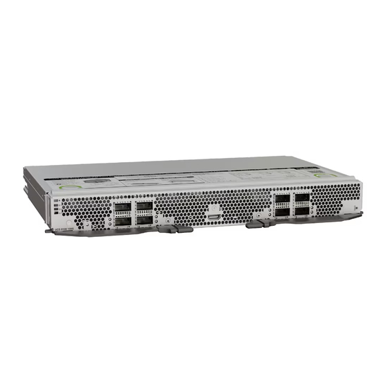
The Cisco UCS X-Series Direct Fabric Interconnect 9108 100G (UCSX-S9108-100G) is a modular fabric interconnect system designed for the Cisco UCS X9508 server chassis. The Cisco UCS X-Series Direct Fabric Interconnect 9108 100G ("fabric interconnect" or "fabric interconnect module" in this document) is part of the overall Cisco UCS X-Series Direct solution, which consists of the fabric interconnect plus additional Cisco equipment that enables end-to-end connectivity. -
Page 10: Fabric Interconnect Front Panel
• Bootup and system firmware log retrieval: USB 2.0 port Type-A connector • Management connectivity: One 10/100/1000 Mbps management port The fabric interconnect is always deployed in pairs in a Cisco UCS X9508 modular system. The UCS X-Series Direct system cannot operate with only one fabric interconnect. - Page 11 Ports 3 and 4 are 100 Gbps Ethernet only, which can be configured as: • 10/25/40/100 Gbps Ethernet Uplink • Appliance • Fibre Channel over Ethernet (FCoE) Uplink Cisco UCS X-Series Direct Fabric Interconnect 9108 100G Installation and Service Guide...
-
Page 12: Interpreting Leds
The fabric interconnect is not receiving power. Fan Status Green The fan module is operational. The fan module is not operational (fan is probably not functional). Dark Fan module is not receiving power. Cisco UCS X-Series Direct Fabric Interconnect 9108 100G Installation and Service Guide... -
Page 13: Port Type Details
Ethernet, Fibre FCoE Port, ance Gbps (FC) over Chanel Break- 10/25/ 10/25/ Ethernet 8/16/32 (FCoE) 40/100 40/100 Break- Gbps QSA, Gbps Gbps 1 to 3 to 7 to Cisco UCS X-Series Direct Fabric Interconnect 9108 100G Installation and Service Guide... - Page 14 Overview Port Type Details Cisco UCS X-Series Direct Fabric Interconnect 9108 100G Installation and Service Guide...
-
Page 15: Installing The Fabric Interconnect
The chassis cannot be used or operated without any fabric interconnects (FIs) or IFMs in place. Installing and Removing the Fabric Interconnect Each Cisco UCS X-Series Direct Fabric Interconnect 9108 100G in the rear of the chassis. They are always deployed in pairs, and the minimum fabric interconnect configuration for each UCS X9508 is two. -
Page 16: Removing The Fabric Interconnect
Step 1 If the Cisco UCS X9508 server chassis that contains the fabric interconnects has a cable management tray, move the cables out of the way. If the cables cannot be moved sufficiently, unplug them and, if necessary, remove the cable management arms. - Page 17 Step 5 Continue sliding the fabric interconnect out of the chassis until it is completely removed. Cisco UCS X-Series Direct Fabric Interconnect 9108 100G Installation and Service Guide...
-
Page 18: Installing The Fabric Interconnect
Insert a fabric interconnect. Go to Installing the Fabric Interconnect, on page Installing the Fabric Interconnect The Cisco UCS X-Series Direct Fabric Interconnect 9108 100G must be deployed in pairs, so there are no fabric interconnect module blanks that can be installed. Caution When working with the fabric interconnect, handle them carefully to avoid damage to the modules, connectors, and pins! Make sure that the modules are level during insertion and slide them into the chassis slowly. - Page 19 Make sure the ejector latch is fully inserted in the front panel. Step 7 If the Cisco UCS X9508 server chassis that contains the fabric interconnect module has a cable management tray, attach Cisco UCS X-Series Direct Fabric Interconnect 9108 100G Installation and Service Guide...
-
Page 20: Fabric Interconnect Configuration
Installing the Top Cable Management Arms. Fabric Interconnect Configuration Cisco UCS X-Series Direct Fabric Interconnect 9108 100G can be configured and managed using the following Cisco management platforms. Cisco Intersight The fabric interconnect can be configured and managed through the Cisco Intersight management platform in Intersight Managed Mode (Cisco Intersight Managed Mode). -
Page 21: Connecting The Fabric Interconnect
When running cables in overhead or subfloor cable trays, we strongly recommend that you locate power cables and other potential noise sources as far away as practical from network cabling that terminates on Cisco equipment. In situations where long parallel cable runs cannot be separated by at least 3.3 feet (1 meter), we recommend that you shield any potential noise sources by housing them in a grounded metallic conduit. -
Page 22: Fabric Interconnect Port Configuration
Fabric Interconnect Port Configuration Port Types The fabric interconnect has the following ports which shall be configured through supported Cisco management platforms: • Uplink port: Also called as border-port. An uplink port is an Ethernet port connecting to a northbound LAN aggregation switch. -
Page 23: Port Breakout
Refer to the following recommended topology to guide you while connecting the fabric interconnect for end-to-end Ethernet. This topology is recommended with either Cisco Nexus 9000 Series switches in VPC or any standard top of rack (ToR) Ethernet switch in MCT (multi-chassis trunking) mode. - Page 24 • This topology is supported, but not recommended, if your deployment uses VPC or MCT. Instead, the previous topology is recommended for deployments that use VPC or MCT. Cisco UCS X-Series Direct Fabric Interconnect 9108 100G Installation and Service Guide...
- Page 25 • ToR switches and uplinks are redundant, but vNICs will experience repinning time after a failover No Top of Rack Switch Redundancy Refer to the following supported topology to guide you while connecting the fabric interconnect for end-to-end Ethernet connectivity. Cisco UCS X-Series Direct Fabric Interconnect 9108 100G Installation and Service Guide...
-
Page 26: Example Fibre Channel San Topologies
End Host Mode 1, With Port Channel Configured Refer to the following recommended topology to guide you while connecting the fabric interconnect for end-to-end connectivity to FC storage. This topology is recommended with either Cisco MDS switches or any standard top of rack (ToR) FC switch. - Page 27 • The fabric interconnect is in FC end-host mode. In this mode, the fabric interconnect uplink ports operate as a node ports (N-Port) while ports on the Cisco MDS switch operate as fabric ports (F-Port). • Port Channel configuration is between an FI and MDS pair per side.
- Page 28 End-Host Mode 2, No Port Channels Refer to the following supported topology to guide you while connecting the fabric interconnect for end-to-end connectivity to FC storage. This topology is not recommended if your deployment does not use Cisco MDS switches.
- Page 29 • The fabric interconnects are configured in FC end-host mode. • No port-channel configuration with non-MDS FC switches. • A virtual SAN (vs An) is not supported due to the absence of a Cisco MDS switch. • Four virtual HBAs (vHBAs) are configured per server for high availability.
-
Page 30: Example Ip San Topologies
• The fabric interconnect is configured in FC switch mode. • Four virtual HBAs (vHBAs) are configured per server for high availability. • FC SAN zones and zone management is supported through Cisco Intersight Managed Mode (IMM) or Cisco UCS Managed Mode (UMM). - Page 31 • For ROCEv2, the no-drop QoS class is required, and PFC must be enabled on the ToR Nexus switch. • Multiple vNICs must be configured on each server for redundancy. Caution Connectivity best practices from the Cisco Nexus switch to vendor IP storage are different for each storage vendor. Direct Connection to IP Storage Array Refer to the following recommended topology to guide you for connecting Ethernet-based IP-SAN storage array directly to the fabric interconnects.
-
Page 32: Connecting A Console To The Fabric Interconnect
Typically, you can use a computer terminal as the console device. On the supervisor modules, you use the console serial port. Cisco UCS X-Series Direct Fabric Interconnect 9108 100G Installation and Service Guide... - Page 33 Before you begin • The Cisco UCS X-Series Direct 9108 100G Fabric Interconnect must be fully installed in the Cisco UCS X9508 chassis, which is connected to a power source, and grounded.
- Page 34 Connecting the Fabric Interconnect Connecting a Console to the Fabric Interconnect Cisco UCS X-Series Direct Fabric Interconnect 9108 100G Installation and Service Guide...
-
Page 35: Servicing The Fabric Interconnect
Installing and Removing the Top Cover The top cover for the Cisco UCS X-Series Direct 9108 100G Fabric Interconnect can be removed to allow access to internal components, some of which are field-replaceable. The top cover has a release button on one side and an emboss on the other side. -
Page 36: Installing The Top Cover
The front edge of the top cover must slide under the edge of the front panel. When the top cover is completely installed, the release button clicks. Cisco UCS X-Series Direct Fabric Interconnect 9108 100G Installation and Service Guide... -
Page 37: Removing The Top Cover
Removing the Fabric Interconnect, on page Step 1 Lay the fabric interconnect flat on an ESD-safe work surface. Step 2 Using your fingers, press the release button until it clicks. Cisco UCS X-Series Direct Fabric Interconnect 9108 100G Installation and Service Guide... -
Page 38: Fabric Interconnect Components
After performing any maintenance work on the fabric interconnect, reinstall the top cover. See Installing the Top Cover, on page Fabric Interconnect Components The Cisco UCS X-Series Direct Fabric Interconnect 9108 100G (UCSX-S9108-100G) has the following board-level components. Cisco UCS X-Series Direct Fabric Interconnect 9108 100G Installation and Service Guide... - Page 39 Port number 5 is the top port in the left port pair of this group, and port number 7 is the top port in the right port pair of the group. Cisco UCS X-Series Direct Fabric Interconnect 9108 100G Installation and Service Guide...
-
Page 40: Instructions
Cisco UCS X-Series Direct Fabric Interconnect Module Field Replaceable Unit Replacement Instructions The rear of the Cisco UCS X9508 contains two module bays for the UCS X-Series Direct Fabric Interconnect 9108 100G (fabric interconnect modules) above the fans. Refer to the following illustration for information about field-replacement options on the fabric interconnect module. -
Page 41: Removing A Fabric Interconnect Fan
Insert a fan module. Go to Installing a Fabric Interconnect Fan, on page Installing a Fabric Interconnect Fan Use this task to install the fan (UCSX-RSFAN=) for a fabric interconnect. Cisco UCS X-Series Direct Fabric Interconnect 9108 100G Installation and Service Guide... -
Page 42: Installing And Removing A Fabric Interconnect M.2 Mini Storage Module
Each mini storage module consists of a sled (or carrier) and a M.2 240G SATA SSD. The M.2 storage module can be interchanged between fabric interconnects in the chassis. The M.2 storage modules are field replaceable, as is the sled. Cisco UCS X-Series Direct Fabric Interconnect 9108 100G Installation and Service Guide... -
Page 43: Mini-Storage Considerations
Use this task to install an M.2 mini storage module into the fabric interconnect's M.2 module carrier. Step 1 Holding the module by the long sides, align the two holes on the module's short side with the retention pins on the M.2 module holder. Cisco UCS X-Series Direct Fabric Interconnect 9108 100G Installation and Service Guide... -
Page 44: Installing And Removing A Mini-Storage Ssd
With the mini-storage module removed from the fabric interconnect, use a #1 Phillips-head screwdriver to remove the single screw that secures the M.2 SSD to the carrier. Step 2 Lift the M.2 SSD from its socket on the carrier. Cisco UCS X-Series Direct Fabric Interconnect 9108 100G Installation and Service Guide... -
Page 45: Installing A Mini Storage Ssd
Press the M.2 drive flat against the carrier. Step 4 Install the single screw that secures the end of the M.2 SSD to the carrier. Figure 10: Showing M.2 Drive Installation Cisco UCS X-Series Direct Fabric Interconnect 9108 100G Installation and Service Guide... - Page 46 Servicing the Fabric Interconnect Installing a Mini Storage SSD Cisco UCS X-Series Direct Fabric Interconnect 9108 100G Installation and Service Guide...
-
Page 47: Recycling Fabric Interconnect Components
Recycling the Fabric Interconnect PCBs, on page 39 Recycling the Fabric Interconnect PCBs Each Cisco UCS X-Series Direct Fabric Interconnect 9108 100G has a printed circuit board (PCB) that is connected to a sheet metal tray. You must: • Disassemble and remove additional parts to gain access to the PCB. - Page 48 Recycling Fabric Interconnect Components Recycling the Fabric Interconnect PCBs Step 2 Remove the stiffener bracket. a) Using a T10 screwdriver, remove the M3 screws. b) Grasp the bracket and remove it. Cisco UCS X-Series Direct Fabric Interconnect 9108 100G Installation and Service Guide...
- Page 49 Using a T8 screwdriver, remove the M3 screws on the exterior of the fabric interconnect. b) Using a T10 screwdriver, remove the M3 screws on the interior of the fabric interconnect. c) Grasp the bracket and remove it. Cisco UCS X-Series Direct Fabric Interconnect 9108 100G Installation and Service Guide...
- Page 50 Grasp each airflow baffle and remove it from the tray. The airflow baffles are attached to the tray by adhesive, so you must pull with enough force to break the adhesion. Cisco UCS X-Series Direct Fabric Interconnect 9108 100G Installation and Service Guide...
- Page 51 Recycling Fabric Interconnect Components Recycling the Fabric Interconnect PCBs b) Using an 8mm hexagonal nut driver, remove the standoffs. c) Using a T10 screwdriver, remove the M3 screws. Cisco UCS X-Series Direct Fabric Interconnect 9108 100G Installation and Service Guide...
- Page 52 Grasp the PCBA and disconnect it from the sheet metal. Step 5 Disconnect the remaining components from the PCBA. a) Using the T10 screwdriver, remove the M3 screws for the top heatsink. Cisco UCS X-Series Direct Fabric Interconnect 9108 100G Installation and Service Guide...
- Page 53 Turn the PCBA over so that the bottom is facing up. c) Using the #1 Phillips screwdriver and remove the M2 screws. d) Using a pliers, release the four heatsink pushpins. Cisco UCS X-Series Direct Fabric Interconnect 9108 100G Installation and Service Guide...
- Page 54 Grasp the plastic bracket for the M.2 module and remove it. g) If the top heat sink is still attached, grasp and remove it. h) Grasp the center heatsink and remove it. Cisco UCS X-Series Direct Fabric Interconnect 9108 100G Installation and Service Guide...
- Page 55 Recycling Fabric Interconnect Components Recycling the Fabric Interconnect PCBs Step 6 Recycle the sheet metal and motherboard in compliance with your local recycling and e-waste regulations. Cisco UCS X-Series Direct Fabric Interconnect 9108 100G Installation and Service Guide...
- Page 56 Recycling Fabric Interconnect Components Recycling the Fabric Interconnect PCBs Cisco UCS X-Series Direct Fabric Interconnect 9108 100G Installation and Service Guide...
-
Page 57: Technical Specifications
Physical Specifications for the Fabric Interconnect, on page 49 • Environmental Specifications for the Fabric Interconnect, on page 49 Physical Specifications for the Fabric Interconnect The following table shows the physical specifications for the Cisco UCS X-Series Direct 9108 100G Fabric Interconnect. Specification Value Height 1.71 in. - Page 58 Technical Specifications Technical Specifications Specification Value Altitude, Operating 0 to 10,000 ft (0 to 3000m); maximum ambient temperature of 30° C Altitude, Non-Operating 40,000 ft (12,000m) Cisco UCS X-Series Direct Fabric Interconnect 9108 100G Installation and Service Guide...
-
Page 59: Appendix B Obtaining Hardware
The following table shows the required hardware to support a fully functioning fabric interconnect. Use the following table when you want to order spares or Cisco UCS X-Series Direct modules to scale out your Cisco UCS X-Fabric deployment. - Page 60 Obtaining Hardware Obtaining Hardware Cisco UCS X-Series Direct Fabric Interconnect 9108 100G Installation and Service Guide...
- Page 61 RJ-45 connectors installing M.2 SSD rollover cable installing, fabric interconnect installing, fabric interconnect fan installing, M.2 mini storage module installing, top cover top cover, installing top cover, removing Cisco UCS X-Series Direct Fabric Interconnect 9108 100G Installation and Service Guide IN-1...
- Page 62 INDEX Cisco UCS X-Series Direct Fabric Interconnect 9108 100G Installation and Service Guide IN-2...
Need help?
Do you have a question about the UCS X-Series Direct Fabric Interconnect 9108 100G and is the answer not in the manual?
Questions and answers