Advertisement
Catalyst 9300/X/L-M Series Installation Guide
About this Guide
This guide provides instruction on how to install and configure your Catalyst 9300/X/L-M series switches in the Meraki-
managed mode.
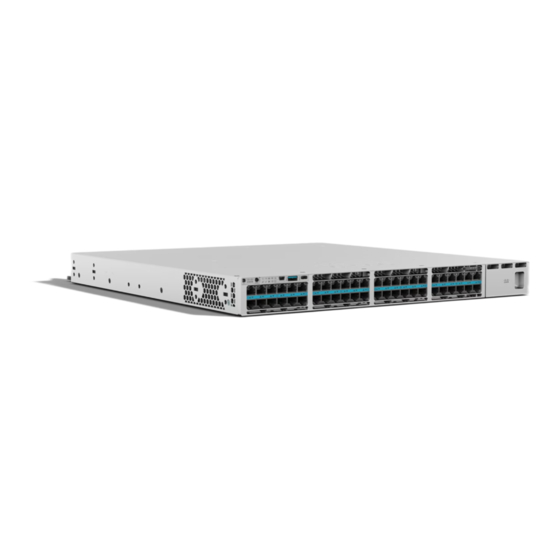
Product Overview
Models
Model number
C9300-24T
C9300-24P
C9300-24U
C9300-24UX
C9300-48T
C9300-48P
C9300-48U
24 port Gbe Data Only
24 port Gbe Data with 30W PoE+
24 port Gbe Data with 60W UPOE
24 port mGig Data with 60W UPOE
(10G/5G/2.5G/1G/100M)
48 port Gbe Data Only
48 port Gbe Data with 30W PoE+
48 port Gbe Data with 60W UPOE
Description
Uplink Config
Modular U
Modular U
Modular U
Modular U
Modular U
Modular U
Modular U
1
Advertisement
Table of Contents

Related Manuals for Cisco Meraki Catalyst 9300/X/L-M Series


Summary of Contents for Cisco Meraki Catalyst 9300/X/L-M Series
- Page 1 Catalyst 9300/X/L-M Series Installation Guide About this Guide This guide provides instruction on how to install and configure your Catalyst 9300/X/L-M series switches in the Meraki- managed mode. Product Overview Models Model number Description Uplink Config C9300-24T Modular U 24 port Gbe Data Only C9300-24P Modular U 24 port Gbe Data with 30W PoE+...
- Page 2 48 port Cisco UPOE, 36 ports 100M/1G/2.5G + 12 ports Multigigabit (10G/ C9300-48UXM Modular U 5G/2.5G/1G/100M) C9300-48UN 48 port 5Gbps Multigigabit UPOE ports (5G/2.5G/1G/100M) Modular U C9300-24S 24 port 1Gbe SFP Modular U C9300-48S 48 port 1Gbe SFP Modular U...
-
Page 3: Technical Specifications
Technical Specifications • Each model has 1 dedicated management interface (Local Status Page access) • The 9300 model has two stack ports supporting (480G), the 9300X supports 1Tbps stacking and is backward compatible with 9300. • The 9300 and 9300X can stack together at 480G. The 9300L can only stack with other 9300L switches. •... - Page 4 C9300-24S 24 x 1GbE SFP 84.6 / 124.3 W Yes, Dual 88.9 / 158.3 C9300-48S 48 x 1 GbE SFP Yes, Dual 12 x 1/10/25 GbE C9300X-12Y 97.1 / 157.3 W Yes, Dual SFP28 24 x 1/10/25 GbE 139.6 / 243.7 C9300X-24Y Yes, Dual SFP28...
-
Page 5: Front Panel Components
48 x 1GbE RJ45 C9300L-48P-4X PoE+/802.3bt 67.40 / 598 W 505W Yes, Dual 4 x 1G/10G SFP+ Uplink 48 x 1GbE RJ45 67.38 / C9300L-48PF-4X PoE+/802.3bt 890W Yes, Dual 1023.56 W 4 x 1G/10G SFP+ Uplink 8 x 100M/1G/2.5G/5G/ 10G mGig 68.98 / 16 x 1G (1G/100M/ C9300L-24UXG-4X... - Page 6 Reports systems status (along with the System LED) Blue Beacon LED Please refer to the LED indicators in the Meraki-managed mode table for details Reset switch to factory settings. Reset (Mode) button Please refer to the Factory Reset Process section for details System LED Reports status of the (along with the Blue Beacon LED) Active LED...
-
Page 7: Back Panel Components
System error: Switch failed to complete local provisioning. Solid amber Switch is completely provisioned but unable to connect Solid amber to Meraki cloud. Firmware download / upgrade in progress Blinking green Solid Blue There is a fault with the power supply, fan, or network module Blinking amber (not traffic-related) Switch is fully operational and connected to the Meraki cloud... - Page 8 its original factory settings. Safety and Warnings These operations are to be taken with respect to all local laws. Please take the following into consideration for safe operation: • Power off the unit before you begin. Read the installation instructions before connecting the system to the power source.
-
Page 9: Assigning An Ip Address
current list of outbound ports and IP addresses for your particular organization can be found under Help → Firewall info. The help button is located on the top right corner of any dashboard page. For more information refer to Upstream Firewall Rules for Cloud Connectivity. -
Page 10: Dynamic Assignment
Dynamic Assignment When using DHCP, the DHCP server should be configured to assign a static IP address for each MAC address belonging to a Meraki switch. Other features of the network, such as 802.1X authentication, may rely on the property that the switches have static IP addresses. -
Page 11: Installation Instructions
Different power LED colors and their interpretation are listed under this section. It may take some time for a device to boot up so refer to the power LED indicators to understand what the switch is doing during boot up. Be patient and let the switch complete the whole boot-up process and connect to the Meraki cloud. - Page 12 3. Secure and screw in the rack mount bracket on to the rack. 4. Insert the Uplink module.
- Page 13 (clockwise direction). Make sure the Cisco logo is on the top side of the connector. • Connect the other end of the cable to the port on the other switch and finger-tighten the screws. Avoid over tightening the screws.
-
Page 14: Basic Troubleshooting
If you are still experiencing hardware issues, please contact Cisco Meraki support by logging in to dashboard and using the Help option near the top of the page, then opening and email case or calling using the contact information on that page. - Page 15 • The equipment is subject to installation and maintenance by specialists with the appropriate qualifications, sufficient specialized knowledge, and skills. • Rules and conditions for the sale of equipment are determined by the terms of contracts concluded by Cisco or authorized Cisco partners with equipment buyers.
Need help?
Do you have a question about the Meraki Catalyst 9300/X/L-M Series and is the answer not in the manual?
Questions and answers