Table of Contents
Advertisement
Quick Links
Advertisement
Table of Contents

Subscribe to Our Youtube Channel
Related Manuals for SystemAir SAVE VSR 700


Summary of Contents for SystemAir SAVE VSR 700
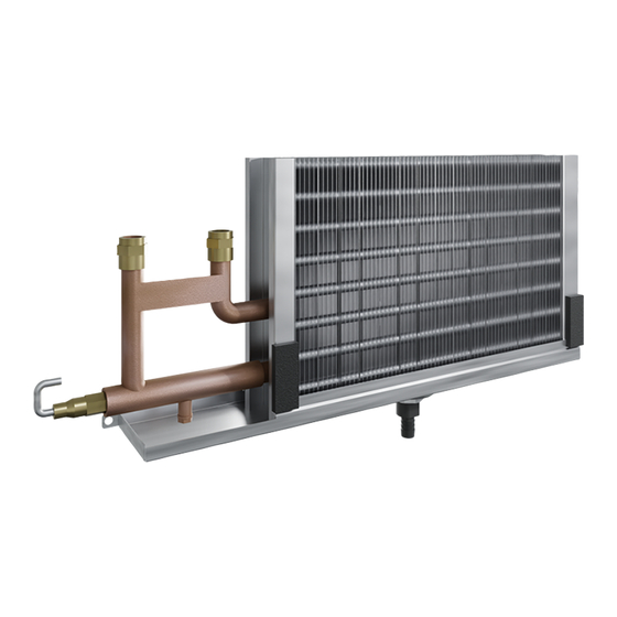
- Page 1 Installation instruction Water coil SAVE VSR 700...
-
Page 2: Table Of Contents
Table of contents 1 Introduction ............1 Product description ........1 Intended use ..........1 Product overview......... 1 2 Safety ..............1 Safety definitions ......... 1 3 Installation............2 To do before the installation of the product............2 To install the product ........2 To configure .......... -
Page 3: Introduction
Safety definitions This product is a water coil with a frost protection sensor de- Warnings, cautions and notes are used to point out specially signed for installation inside the SAVE VSR 700. important parts of the manual. Warning Intended use If you do not obey these instructions, there is a risk of death or injury. -
Page 4: Installation
• Make sure that the installation location has the access to the drainage system. • Make sure to disconnect the SAVE VSR 700 from the power supply. To install the product Disconnect the fan cables. The cables can be found next to the fan. - Page 5 Remove the screws from the wall in the corners. Put the water coil on the rails. Pull out the wall. Attach the water coil with the two screws. Disconnect the electrical heater power cable and the overheat protection sensor cable (OHT). Remove the two screws that hold the electrical heater to the wall.
- Page 6 Remove the screw from the control board cover. 11 Connect the water circulation pipes to the water coil inlet and outlet pipes. Remove the screw to release the control board for the better access if necessary. Put the frost protection sensor (FPT) cable through the free rubber grommet.
-
Page 7: To Configure
13 Connect the valve actuator control cable to the analogue output 3 (AO3) on the connection board. Caution Do not use the 24 V DC output on the connection board to power the actuator. 14 Install the control board if it was removed. Install the con- trol board cover. -
Page 8: Technical Data
Technical data Technical data overview Design temperature — min/max, °C –40/110 Design pressure — min/max, barg –1 /16 Test pressure, barg Volume, L 0,43 Fluid type O, Glycol Product dimensions 67,5 Ø1/2” M FPT 1/4” Ø1/8” Ø16 (1/2”) 475,5... -
Page 9: Eu Declaration Of Conformity
EU Declaration of conformity We, the manufacturer Company Systemair UAB Address Linų g. 101 LT–20174 Ukmergė LITHUANIA declare under our sole responsibility that the product Product Water coil designation Type/Model Water coil VSR 700 fulfils the relevant provisions of following directives and... - Page 10 © Copyright Systemair AB All rights reserved Systemair AB reserves the rights to alter their products without notice. This also applies to products already ordered, as long as it does not affect the previously agreed specifications. Document in original language...
Need help?
Do you have a question about the SAVE VSR 700 and is the answer not in the manual?
Questions and answers