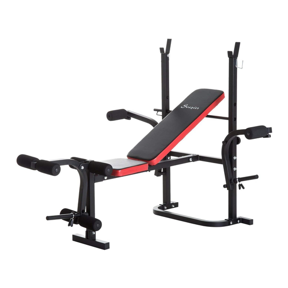
Summary of Contents for Soozier A91-054
- Page 1 IN230800273V01_US_CA A91-054 IMPORTANT, RETAIN FOR FUTURE REFERENCE: READ CAREFULLY ASSEMBLY INSTRUCTION...
- Page 2 18 24 UMBER ESCRIPTION Upright Main beam Front upright Cross beam Front Stabilizer Pivot Bar Cross bar Leg extension bracket Fly arm Foam tube Foam tube Fix locking Spring locking Seat Backrest End cap End cap End cap End cap End cap...
- Page 3 Protect cap Protect cap Foam “U” Rear stabilizer Knob Knob Screw 8 x 50 mm Screw 10 x 60 mm Screw 10 x 60 mm Screw 8 x 40 mm Screw 8 x 20 mm Screw 10 x 120 mm Screw 8 x 45 mm Washer 8 x 16 x 1,5 mm...
- Page 4 Pre Assembled Pre Assembled Pre Assembled Pre Assembled Pre Assembled Pre Assembled Pre Assembled M8x50 M10x60 M10x60 M8x40 M8x20 M10x120 M8x45 M8x55...
- Page 5 SSEMBLY Fix the two uprights (1) to the “U” rear stabilizer (25) use 4 sets of screw (28), washer (36) STEP 1 and nut (41), connect the cross beam (4) to the two uprights (1) use 4 sets of screw (28), washer (36) and nut (41), attach the main beam (2) to the center of the cross beam (4) use one set of screw (29),knob (27) and one set of screw (44),knob (26).
- Page 6 STEP 3 Attach the foam (24) to the foam tube (10), insert the foam tube to the fl y arm (9) use one set of screw (35), washer (36) and nut (41), then fi x the two fl y arms to the two uprights (1) use 2 sets of screw (34), washer (37), and knob (38), and attach the protect cap (43) on the screw (30).
-
Page 7: Instructions D'assemblage
IN230800273V01_US_CA A91-054 IMPORTANT - CONSERVEZ CES INFORMATIONS POUR VOTRE CONSULTATION ULTÉRIEURE: LISEZ ATTENTIVEMENT INSTRUCTIONS D'ASSEMBLAGE... - Page 8 Liste de pièces: 18 24 La description Numéro Vertical Faisceau principal Support avant Barre transversale Stabilisation avant Barre pivot Barre transversale Support d'extension de jambe Bras de mouche Tube en mousse Tube en mousse Fixer le verrouillage Verrouillage à ressort Siège Dossier Capuchon d'extrémité...
- Page 9 Capuchon d'extrémité Capuchon de protection Capuchon de protection Mousse "U" stabilisateur arrière bouton bouton Vis 8 x 50 mm Vis 10 x 60 mm Vis 10 x 60 mm Vis 8 x 40 mm Vis 8 x 20 mm Vis 10 x 120 mm Vis 8 x 45 mm Rondelle 8x16x1,5mm Rondelle 10 x 20 x 2 mm...
- Page 10 Pré assemblé Pré assemblé Pré assemblé Pré assemblé Pré assemblé Pré assemblé Pré assemblé M8x50 M10x60 M10x60 M8x40 M8x20 M10x120 M8x45 M8x55...
- Page 11 Assemblée ÉTAPE 1 Fixez les deux montants (1) au stabilisateur arrière "U" (25) utilisez 4 ensembles de vis (28), la rondelle (36) et l'écrou (41), reliez la traverse (4) aux deux montants (1) Utiliser 4 ensembles de vis (28), rondelle (36) et écrou (41), fixer le faisceau principal (2) au centre de la traverse (4) utiliser un jeu de vis (29), le bouton (27) et Un jeu de vis (44), le bouton (26).
- Page 12 ÉTAPE 3 Fixez la mousse (24) au tube de mousse (10), insérez le tube de mousse dans le bras de la mouche (9) utilisez un jeu de vis (35), la rondelle (36) et l'écrou (41), puis fixez les deux bras de mouche Sur les deux montants (1), utilisez 2 jeux de vis (34), la rondelle (37) et le bouton (38) et fixez le capuchon de protection (43) sur la vis (30).


Need help?
Do you have a question about the A91-054 and is the answer not in the manual?
Questions and answers